Method for determining acceleration factors in EM testing structure

A technology of test structure and acceleration factor, which is applied in the direction of electronic circuit test, measuring circuit, measuring device, etc., can solve the problems of occupying too many experimental resources and cumbersome operation, and achieve the effect of saving experimental resources

Active Publication Date: 2010-12-22
SHANGHAI HUAHONG GRACE SEMICON MFG CORP
View PDF0 Cites 16 Cited by
  • Summary
  • Abstract
  • Description
  • Claims
  • Application Information

AI Technical Summary

Problems solved by technology

Although this method solves the deviation caused by Joule heat in the push-N experiment of the traditional method, it is cumbersome to operate and still takes up more experimental resources (because this method is based on the traditional method, it still needs to use at least 3 (times) Ea and N can only be deduced from the furnace chamber and 5 sets of experiments

Method used


Image

  • Method for determining acceleration factors in EM testing structure
  • Method for determining acceleration factors in EM testing structure
  • Method for determining acceleration factors in EM testing structure

Examples


Embodiment Construction

[0032] The method of determining the acceleration factor in the EM test structure of the present invention is also carried out in a commonly used furnace chamber, which is to set the temperature of the furnace chamber at a fixed temperature, and add different current densities to the EM test structure. carry out testing.

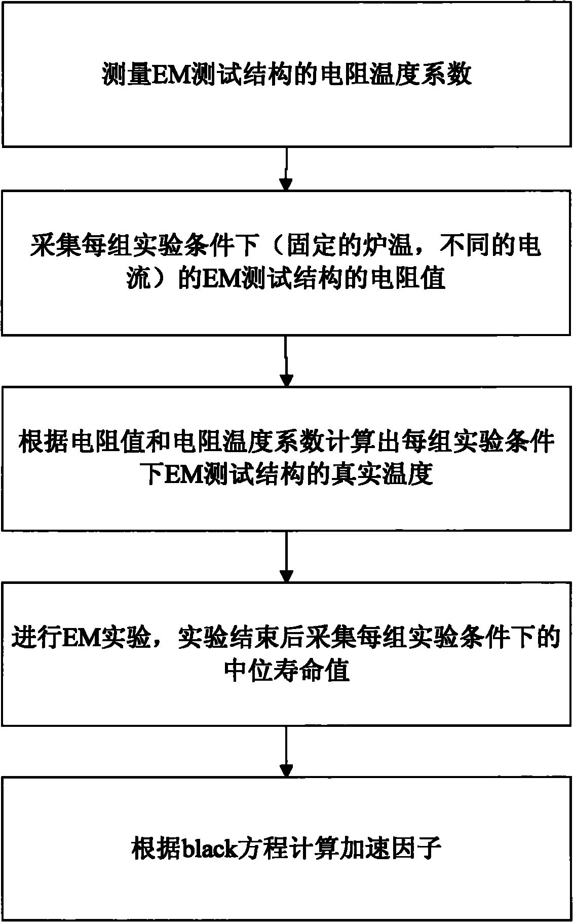
[0033] Such as image 3 As shown, the present invention includes the following steps:

[0034] First, in the process of heating the furnace chamber to the set temperature, measure the voltage across the EM test structure at a certain temperature through a small current, and then calculate the resistance, and calculate the EM based on the temperature and the measured resistance. Test the temperature coefficient of the structure.

[0035] In the above process, in order to accurately measure the temperature coefficient of resistance, in addition to using some resistance-temperature data, it is also necessary to control the size of the current, so that no Joule heat ...


PUM


Abstract

The invention discloses a method for determining acceleration factors in an EM test structure. The method comprises the following steps: measuring the resistance temperature coefficient of the EM test structure by adopting current which cannot cause Joule heat on the EM structure in a furnace temperature rising process; 2, accelerating current in the condition of at least three groups of current after the furnace is heated to a preset temperature, wherein at least two groups ensure that the EM test structure generates different Joule heats, and measuring the resistance value of the EM test structure under the condition of different currents; 3, calculating the actual temperature of the EM test structure under the condition of different currents according to the resistance temperature coefficient an the resistance value; 4, performing EM experiment, and acquiring the center life of each group under the experimental condition after the experiment is completed; and 5, calculating the acceleration factors according to a black equation by using the actual temperature value and the current condition of the EM test structure and the center life. The method can reduce the cost for measuring two acceleration factors Ea and N of the EM test structure, and improves the production efficiency.

Description

Technical field [0001] The invention relates to the field of semiconductor integrated circuit testing, in particular to a method for determining acceleration factors in an EM testing structure. Background technique [0002] Ea and N are the temperature activation energy and current acceleration factor of the EM (EM: Electro-Migration) test structure, respectively. Corresponding to different processes, different structures or different materials, the temperature activation energy Ea and the current acceleration factor N will be different. Therefore, for new processes, new structures or new materials, Ea and N must be re-derived in order to more accurately derive the service life of the EM test structure. [0003] The traditional method to obtain the two acceleration factors of the EM test structure is the 3J3T experiment (refer to the "Standards of the Joint Committee of Electronic Device Engineering", 1998.2, "Standard Method for Calculating the Current Density and Temperature Par...

Claims


Application Information

Patent Timeline
Patent Type & Authority Applications(China)
IPC IPC(8): G01R31/00G01R31/28G01R27/02G01R27/08
Inventor 张会锐陈建钢
Owner SHANGHAI HUAHONG GRACE SEMICON MFG CORP
Why Eureka
Try Eureka