Electromagnetic coil and method for processing coil terminal thereof

A technology of electromagnetic coils and terminals, applied in the direction of coils, coil manufacturing, circuits, etc., can solve the problems of difficulty in confirming twisting processing, increased manufacturing costs, and low reliability of wire strengthening operations, so as to improve reliability and suppress external force breaking. line effect

Active Publication Date: 2010-12-22
FUJI ELECTRIC FA COMPONENTS & SYST CO LTD
View PDF4 Cites 10 Cited by
  • Summary
  • Abstract
  • Description
  • Claims
  • Application Information

AI Technical Summary

Problems solved by technology

[0014] According to the strengthening measures for the winding terminal portion of the lead wire type electromagnetic coil described above, since the process of forming the coil winding and the terminal treatment process of reinforcing the winding terminal are different processes, it is possible to confirm the terminal treatment state and improve the reliability of the strengthening operation. However, if the wire diameter of the winding wire becomes thicker to a certain extent, not only the work of winding the terminal of the coil winding on the lead wire becomes difficult, but also the manufacturing cost becomes lower compared with the stranded wire method. big problem
[0015] In addition, compared w

Method used


Image

  • Electromagnetic coil and method for processing coil terminal thereof
  • Electromagnetic coil and method for processing coil terminal thereof
  • Electromagnetic coil and method for processing coil terminal thereof

Examples


Embodiment

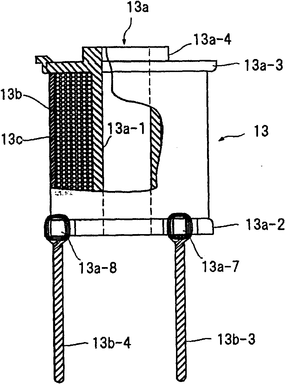
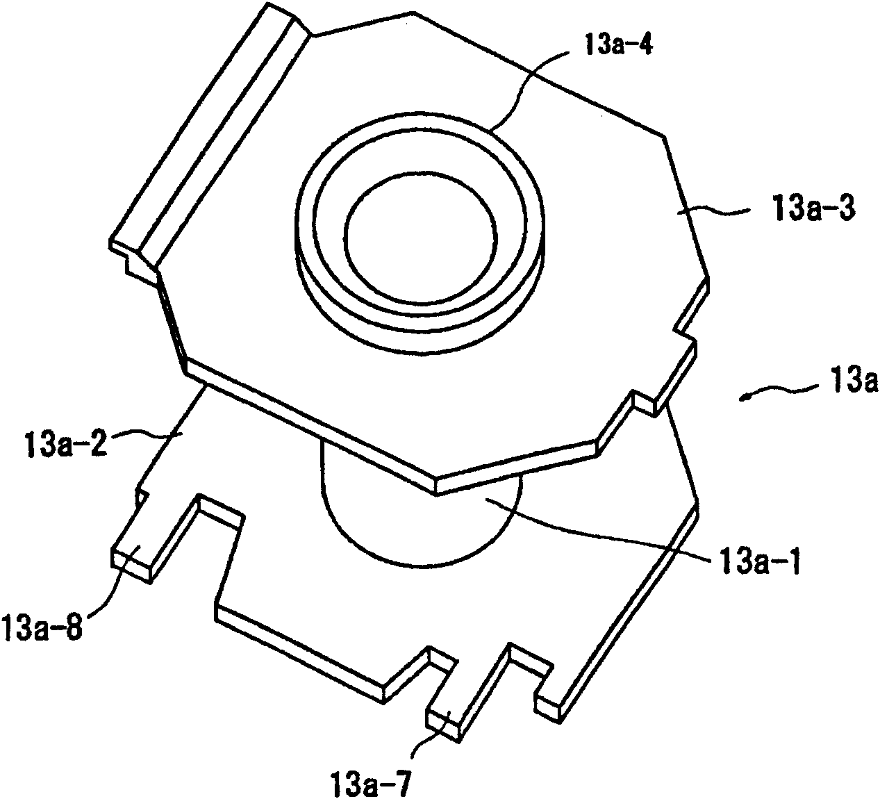
[0039] Figure 1 to Figure 3 represent the present invention. figure 1 is a partially cutaway configuration diagram showing an electromagnetic coil device according to an embodiment of the present invention, figure 2 It is a figure which shows the coil winding terminal processing process for strengthening the coil winding terminal of the embodiment of the present invention, image 3 It is a perspective view showing the skeleton structure of the coil used in the present invention.

[0040] exist Figure 1 to Figure 3In , the parts that are the same as those of the conventional device are denoted by the same symbols. In the above figure, the electromagnetic coil device 13 includes a coil skeleton 13a formed by an insulating resin mold, and a coil winding 13b formed by winding a winding wire on the coil skeleton with a desired number of turns. The outer circumference of the coil winding 13b is covered for protection. The winding start end portion 13b-1 and the winding end ...


PUM


Abstract

The invention aims to provide an electromagnetic coil device and a method for processing a winding terminal thereof. Even a coil winding made of thin wires can be also provided with a reinforced winding terminal part with high reliability. In addition, a coil winding made of wires with even a, more or less, large diameter can also easily achieve the operation strengthening. The solution method is that the periphery of a flange of a coil frame for winding a coil winding is provided with clamping sheets for clamping and stopping a coil winding terminal and for wires which, of a winding starting terminal part and a winding stopping terminal part of the coil winding winded on the coil frame, extends towards the outer side of the flange, base end sides thereof are clamped on the clamping sheets and are folded back for many times to form a folding-back wire bundle which has a specific length and is twirled for appropriate times for twisting to become a leading-out terminal sheaved and fixed on the clamping sheets of the flange of the coil frame.

Description

technical field [0001] The present invention relates to an electromagnetic coil used in an overcurrent electromagnetic tripping device of a circuit breaker and a method for processing the coil terminal. Background technique [0002] As shown in Patent Document 1, an electromagnetic trip device is incorporated in a circuit breaker. The electromagnetic trip device detects the circuit current, and when the detected current becomes overcurrent, trips the latch of the switching mechanism to interrupt the circuit current. . [0003] When this electromagnetic tripping device is incorporated into the resin molded case of the circuit breaker to assemble the circuit breaker, in order to simplify the assembly work, the electromagnetic tripping device is formed and configured in advance in the resin molded case divided into two parts. The positioning seat corresponding to the yoke, iron core, electromagnetic coil and other components of the device, in the process of assembling the circ...

Claims


Application Information

Patent Timeline
IPC IPC(8): H01F5/04H01F41/04
Inventor 江村武史
Owner FUJI ELECTRIC FA COMPONENTS & SYST CO LTD
Why Eureka
Try Eureka