Modular multifunctional electrical appliance

A multi-functional and modular technology, applied in the direction of circuits, electrical components, protection switch parts, etc., can solve unreasonable and inability to meet site requirements and other problems, achieve high economic and social benefits, reduce volume and installation size , Easy to install and use

Active Publication Date: 2010-12-22
浙江中凯科技股份有限公司
View PDF1 Cites 16 Cited by
  • Summary
  • Abstract
  • Description
  • Claims
  • Application Information

AI Technical Summary

Problems solved by technology

In this case, still using CPS with bimetallic thermal magnetic protection can no longer meet the requirements, but it is unreasonable
With the development of electronic technology and digital technology, low-voltage electrical appliances have been developing in the direction of intelligence, multi-function, and networking. CPS using bimetallic thermal-magnetic protection can no longer meet site requirements.

Method used


Image

  • Modular multifunctional electrical appliance
  • Modular multifunctional electrical appliance
  • Modular multifunctional electrical appliance

Examples


Embodiment Construction

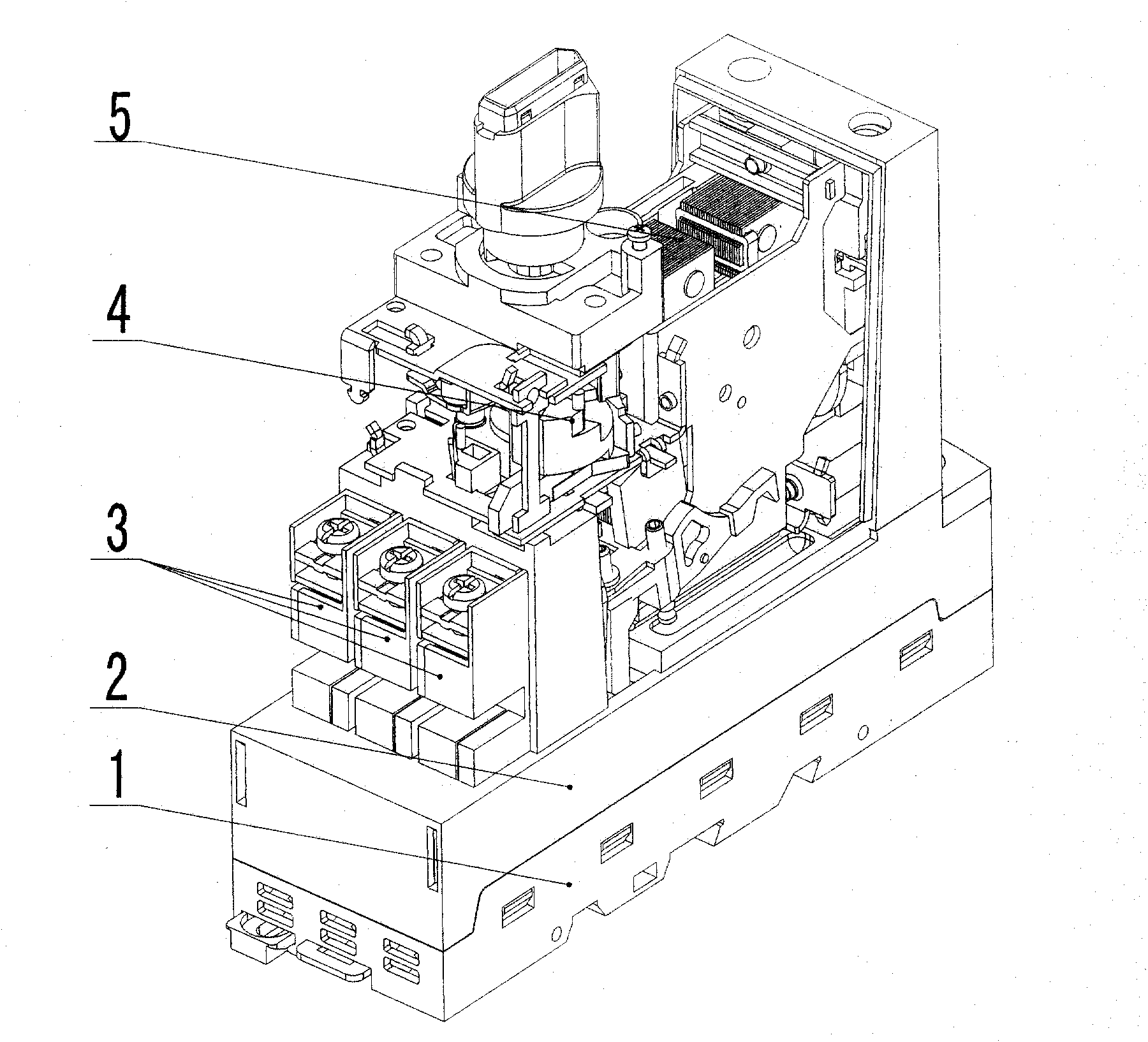
[0035] refer to figure 2 , which is a schematic diagram of the composition of the multifunctional electric appliance of the present invention.

[0036] As shown in the figure: the multi-functional electrical appliance includes: a base (1), a drive case (2), an electromagnetic transmission mechanism (5), an operating mechanism (4), and a contact group (3).

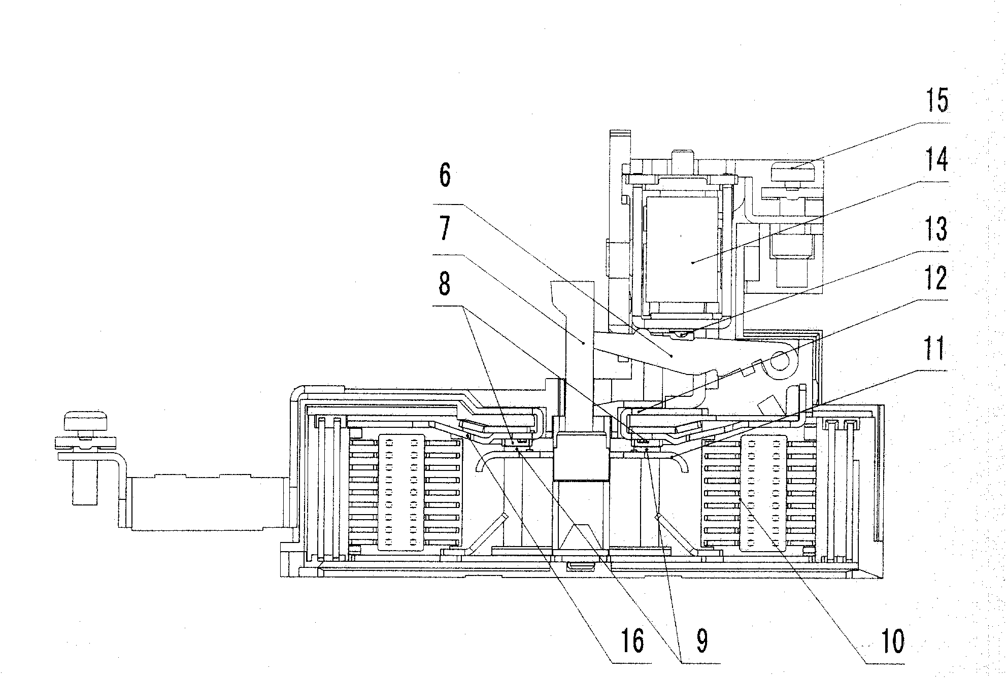
[0037] refer to image 3 , which is a schematic diagram of the contact group of the multifunctional electrical appliance of the present invention.

[0038] As shown in the figure: 14 is a solenoid electromagnet, the coil of which is directly connected to the main circuit, the rod 13 is fixed on the moving iron core of the solenoid electromagnet 14, and the push rod 6 is located below the rod 13 and is associated with the fixed contact bridge 11 The contact supports 7, the double moving contact 9 is welded on the two ends of the contact bridge 11, and the double static contact 8 is welded on the two contact plates 12 and ...


PUM


Abstract

The invention relates to a modular multifunctional electrical appliance, which comprises a base (1), a shell (2), an electromagnetic driving mechanism (5), an operating mechanism (4) and a main circuit contact group (3). The rear end of the main circuit contact group (3) is provided with a wiring terminal and can be connected to a load by a wire or conductive bus; and the inside surface of the rear end of the shell is jointed with the inside surface of the rear end of the main circuit contact group (3). The modular multifunctional electrical appliance also may comprise an auxiliary module, a thermomagnetic tripping device, a digital controller and an isolating mechanism. The modular multifunctional electrical appliance adopts a modular structure design, so different kinds of products can be assembled by using different modules. The volume of the electrical appliance is small. The control and protection coordinate combination is realized in the product. The wiring of the electrical appliance is convenient. The reliability of the electrical appliance is high. And the electrical appliance has the characteristic of saving energy and material and has high economic and social benefits.

Description

technical field [0001] The invention relates to an electrical appliance, in particular to a modularized multifunctional switching appliance, which belongs to the field of low-voltage electrical appliances. Background technique [0002] The electrical system composed of general low-voltage electrical appliances mainly has two methods: one is to realize the protection function (power distribution device, mainly circuit breaker) and control function (control device, mainly contactor and thermal relay or motor protector). ) composed of discrete switching appliances, the two appliances are independently installed and fixed, and are electrically connected through connectors to control and protect between the power supply and the load. figure 1 It is a typical circuit of the above implementation. The isolating switch G in the figure is to ensure the safety of the maintenance personnel when repairing the circuit; the circuit breaker CB (or fuse R) is used as the short circuit prote...

Claims


Application Information

Patent Timeline
Patent Type & Authority Applications(China)
IPC IPC(8): H01H71/00H01H71/08H01H71/10H01H71/40H01H83/00
Inventor 郭其一黄世泽王文均李华民屠瑜权
Owner 浙江中凯科技股份有限公司
Why Eureka
Try Eureka