Eureka AIR delivers breakthrough ideas for toughest innovation challenges, trusted by R&D personnel around the world.

Uplink/downlink antenna pulling away device, transmitter, receiver and channel measuring method

A transmitter and antenna technology, applied in the field of uplink/downlink antenna remote devices, to achieve the effect of flexible measurement

Active Publication Date: 2010-12-22
BEIJING UNIV OF POSTS & TELECOMM
View PDF3 Cites 18 Cited by
  • Summary
  • Abstract
  • Description
  • Claims
  • Application Information

AI Technical Summary

Problems solved by technology

[0005] Traditional channel measurement methods and devices can only be used for single-link channel measurement

Method used


Image

  • Uplink/downlink antenna pulling away device, transmitter, receiver and channel measuring method
  • Uplink/downlink antenna pulling away device, transmitter, receiver and channel measuring method
  • Uplink/downlink antenna pulling away device, transmitter, receiver and channel measuring method

Examples


Embodiment Construction

[0030] The invention will be described in more detail hereinafter with reference to the accompanying drawings, in which exemplary embodiments of the invention are illustrated. In the drawings, the same reference numerals denote the same or similar components or elements.

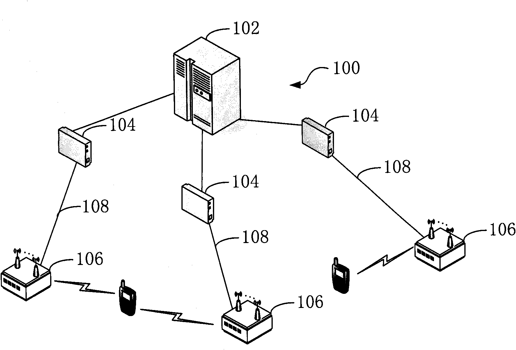
[0031] figure 1 It is a schematic structural diagram of a distributed multi-link multi-antenna broadband channel measurement system 100 according to an embodiment of the present invention. The distributed multi-link multi-antenna broadband channel measurement system 100 includes a main control device 102 , a port 104 , an antenna remote unit 106 and an optical fiber 108 .

[0032] The main control device 102 can be used for scheduling switching time slots of each port 104, and managing and allocating wireless resources. In the distributed multi-link multi-antenna broadband channel measurement system 100, the antenna array can be arranged according to the channel measurement task (for example, urban macro c...


PUM


Abstract

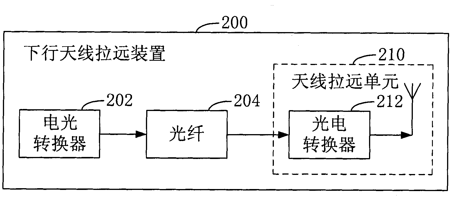
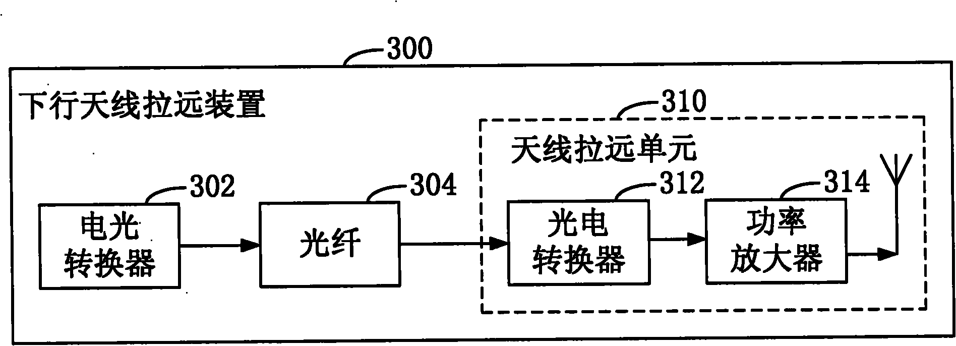
The invention provides an uplink / downlink antenna pulling away device, transmitter, receiver and channel measuring method, relating to the channel measuring technology. The downlink antenna pulling away device used for distributed multilink multiple antenna broadband channel measuring system comprises an electro-optic converter used for modulating a radio frequency signal emitted by the transmitting unit of the distributed multilink multiple antenna broadband channel measuring system into an optical signal, an optical fiber which is connected with the electro-optic converter and is used for transmitting the optical signal generated by modulation of the electro-optic converter as well as an antenna pulling away unit which is connected with the optical fiber, comprises an optic-electro converter connected with the optical fiber and is used for receiving the optical signal transmitted by the optical fiber and demodulating the optical signal into the radio frequency signal. By the embodiment of the invention, the measuring on distributed channel can be more flexible and convenient.

Description

technical field [0001] The invention relates to channel measurement technology, in particular to an uplink / downlink remote antenna device, a transmitter, a receiver and a channel measurement method. Background technique [0002] Under the traditional cellular network architecture, single-link multiple-input multiple-output technology has become one of the mainstream standards of the new generation of wireless communication systems. It is difficult for users to achieve the same spectral efficiency and quality of service (QoS) level as users in the center of the cell. Therefore, the transmitting antenna on the base station side must increase the RF output power to effectively ensure the coverage of users in the edge cell, which increases the output energy consumption virtually. Adapt to the needs of future green communication development. In addition, traditional cells must provide good power control, radio resource management, and handover scheduling when users move at high ...

Claims


Application Information

Patent Timeline
Patent Type & Authority Applications(China)
IPC IPC(8): H04B17/00H04B10/08H04B1/04H04B1/16H04B10/2575H04B17/15H04B17/29H04B17/309
Inventor 张建华张平张煜熊飞王强
Owner BEIJING UNIV OF POSTS & TELECOMM
Why Eureka
Eureka Blog
Learn More