Craniotomy drill

一种颅钻、减速器的技术,应用在医药科学、手术等方向,能够解决增加开颅钻整体重量、壳体上部体积大、事故等问题,达到结构简单、锁紧与松开简单、减轻整体重量的效果

Inactive Publication Date: 2010-12-29
CHONGQING RUNZE PHARM CO LTD
View PDF11 Cites 8 Cited by
  • Summary
  • Abstract
  • Description
  • Claims
  • Application Information

AI Technical Summary

Problems solved by technology

However, this structure causes the upper part of the shell to be larger, which increases the overall weight of the craniotomy drill. At the same time, after a long time of use, the tightening screw becomes loose, and the motor will slide out of the receiving cavity, which may easily cause accidents during surgery.

Method used


Image

  • Craniotomy drill
  • Craniotomy drill
  • Craniotomy drill

Examples


Embodiment Construction

[0020] The present invention will be further described below in conjunction with accompanying drawing and specific embodiment:

[0021] Such as Figure 1 to Figure 5 Shown:

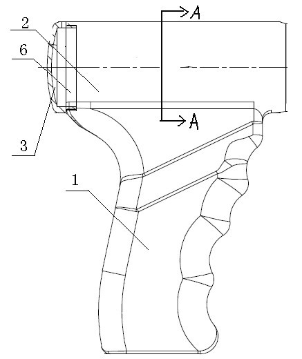
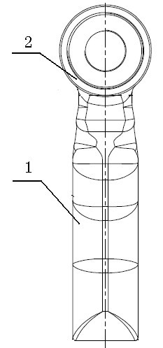
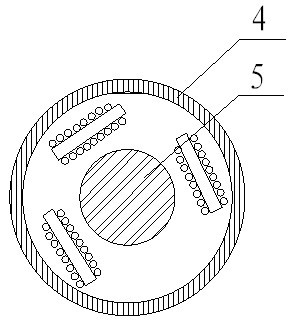
[0022] A craniotomy drill, including a main engine, a reducer and a locking seat that are screwed in sequence, and a rotating head transmission rod connected to the output shaft of the reducer is inserted in the locking seat, including a lower handle 1 and an upper receiving part 2 The accommodating part 2 has a stator and a rotor 5 of the DC motor, and the wall 4 of the accommodating part 2 is the casing of the DC motor stator. A perforated baffle plate 6 is provided at the rear of the housing part 2, which divides the housing part 2 into two cavities, the front cavity is provided with a motor stator, and the end cover 3 is tightly connected to the rear end of the housing part 2 through threads; DC The wire on the motor stator passes through the hole on the baffle plate 6, and enters the inside of the ...


PUM


Abstract

The invention discloses a craniotomy drill, comprising a host machine, a speed reducer and a locking base which are in threaded connection in turn; a drill transmission rod connected with the output shaft of the speed reducer is inserted in the locking base; the craniotomy drill is characterized in that the host machine comprises a handle (1) at the lower side and a containing part (2) at the upper side; containing part (2) is internally provided with a stator having a DC motor and a rotor (5); and the wall (4) of the containing part (2) is the outer housing of the DC motor stator. The craniotomy drill has simple structure, and the wall of the containing part is directly used as the outer housing of the motor stator, thereby reducing the volume and reducing the entire weight. The craniotomy drill can prevent the motor from being slid off and can have comparatively high safety performance. Simultaneously, the craniotomy drill has integrated design and comparatively excellent waterproofperformance because of waterproof material and technique.

Description

technical field [0001] The invention relates to a bone drill motor used in surgical operations. Background technique [0002] In surgery, the craniotomy drill is a more commonly used craniotomy tool. The craniotomy drill includes a host, a reducer, a locking seat and a drill bit, and the host includes a housing with a handle at the bottom, a cylindrical housing at the top, and a cylindrical motor. When assembling, it is necessary to plug the motor into the cavity of the cylindrical housing on the upper part of the housing, and then fix the motor with the tightening screws. However, this structure causes the upper part of the shell to be larger, which increases the overall weight of the craniotomy drill. At the same time, after a long time of use, the tightening screw becomes loose, and the motor will slide out of the receiving cavity, which may easily cause accidents during surgery. . Contents of the invention [0003] The purpose of the present invention is to provide ...

Claims


Application Information

Patent Timeline
Patent Type & Authority Applications(China)
IPC IPC(8): A61B17/16
CPCA61B17/1626A61B17/162A61B17/1628A61B17/1695
Inventor 叶雷周健冯华李飞祝恒洋李从晓
Owner CHONGQING RUNZE PHARM CO LTD
Why Eureka
Try Eureka