Light irradiation device
A technology of light irradiation device and point light source, applied in printing device, printing, printing machine, etc., can solve the problem of insufficient curing, and achieve the effect of reducing attenuation and improving peak illuminance
- Summary
- Abstract
- Description
- Claims
- Application Information
AI Technical Summary
Problems solved by technology
Method used
Image
Examples
no. 1 approach
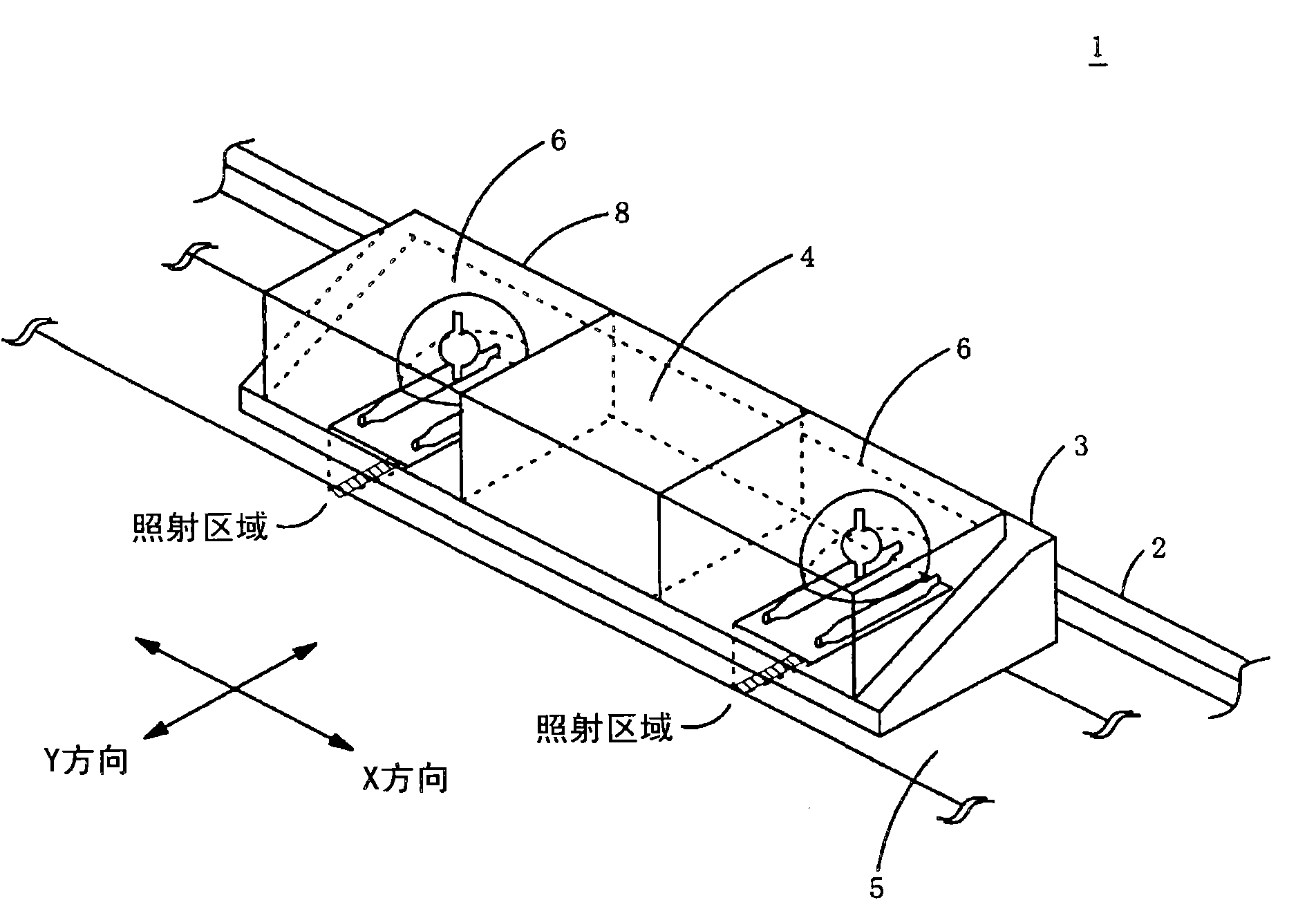
[0058] figure 1 It is a perspective view showing a schematic structure of the head of the inkjet printer of the present invention. In this figure, for ease of understanding, the inside of the light irradiation device can be seen in the figure, and some optical components are omitted.
[0059] The inkjet printer 1 has a bar-shaped guide rail 2 on which a carriage 3 is supported. The carriage 3 reciprocates on the substrate 5 along the guide rail 2 (X direction) by the carriage driving mechanism.
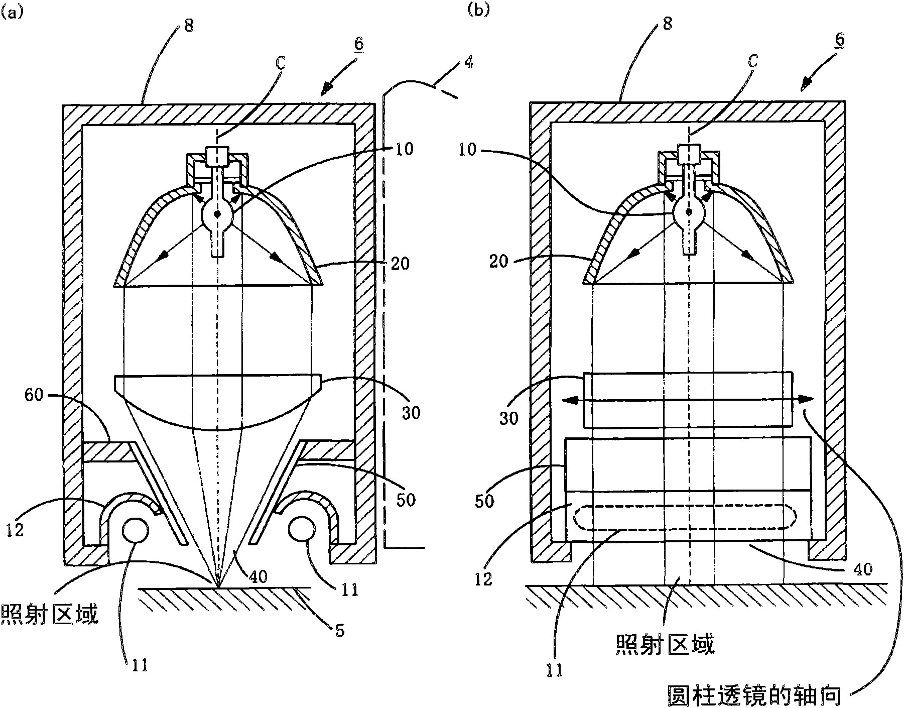
[0060] On the carriage 3 is mounted a recording head 4 provided with nozzles for ejecting ink. Light irradiation devices 6 are provided on both sides of the recording head 4 along the moving direction of the carriage 3 . On the light irradiation device 6, a point light source and a linear light source having different emission wavelength peaks as described later are provided, and the ink, which is the liquid material ejected from the nozzle of the recording head 4 to the base materi...
no. 2 approach
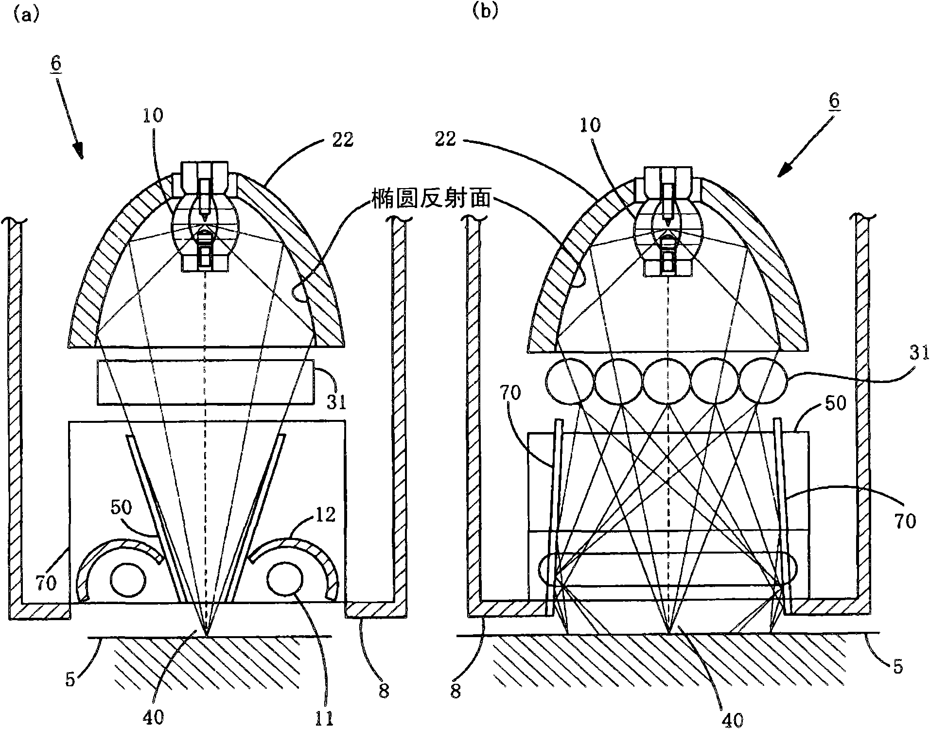
[0091] In the first embodiment, the cylindrical lens 30 is used as the condensing means, but in the second embodiment, a plurality of rod lenses 31 are used. image 3 A cross-sectional view showing a light irradiation device according to a second embodiment. (a) of the figure is a cross-sectional view in the X direction (direction along the moving direction of the head), and (b) is a cross-sectional view in the Y direction (direction perpendicular to the moving direction of the head).
[0092] In this embodiment, on the light exit side of the reflector 22 , a plurality of rod lenses 31 are arranged in parallel contact on a plane perpendicular to the optical axis of the light reflected by the reflector 22 .
[0093]The light emitted from the discharge lamp 10 is reflected by the spheroidal reflective surface of the reflector 22 , becomes light condensed on the second focal point of the reflector 22 , and enters the plurality of rod lenses 31 . Among the lights emitted from the...
no. 3 approach
[0100] In the first and second embodiments, discharge lamps are used as point light sources, but in the third embodiment, light-emitting elements (hereinafter referred to as LEDs) are used as point light sources, but unnecessary visible light and infrared radiation are very few, which is the same in the three embodiments.
[0101] Figure 4 (a) shows a configuration example of a light source portion when an LED is used as a point light source. As shown in the figure, on the metal substrate 16, for example, nine LED packages 13 are arranged linearly. A heat sink is mounted on the surface of the metal substrate 16 opposite to the surface on which the LED package 13 is mounted.
[0102] As for the LED, for example, a current of 1.5 A, a voltage of 35 V, a power of 52 W, and an output of 5 W of ultraviolet light having a wavelength of 365 nm are used.
[0103] A cylindrical lens 15 is mounted on the emission side of the LED package 13 .
[0104] Figure 4 (b) is to use Figu...
PUM
 Abstract
Description
Claims
Application Information
 - R&D Engineer
- R&D Manager
- IP Professional
- Industry Leading Data Capabilities
- Powerful AI technology
- Patent DNA Extraction
Browse by: Latest US Patents, China's latest patents, Technical Efficacy Thesaurus, Application Domain, Technology Topic, Popular Technical Reports.
© 2024 PatSnap. All rights reserved.Legal|Privacy policy|Modern Slavery Act Transparency Statement|Sitemap|About US| Contact US: help@patsnap.com


