
Method for lapping and anchoring fiber sheet around rod to reinforce structural component

A fiber sheet and reinforcement structure technology, which is applied in bridge reinforcement, building maintenance, bridge repair, etc., can solve the problem of unreliable conventional sticking effect of U-shaped fiber sheet, peeling and damage of fiber cloth end, and unreliable effect, etc. problems, and achieve the effect of overcoming the easy peeling off by force, improving the utilization rate of fiber strength, and reliable effect

Inactive Publication Date: 2011-09-28
CENT SOUTH UNIV
View PDF0 Cites 6 Cited by
  • Summary
  • Abstract
  • Description
  • Claims
  • Application Information

AI Technical Summary

Problems solved by technology

However, this method requires the use of thermoplastic fiber sheets that are currently difficult to find in China and are more expensive, and like the above-mentioned ordinary sealing paste, it is often difficult to implement due to the limitation of reinforcement conditions.
In fact, when the closed fiber sheet is allowed to be used on site, ordinary paste can also achieve effective self-anchoring, and common thermosetting fiber sheets can also be used. The method of Lees et al. has no advantage
At present, there is no report on the anchoring of U-shaped fiber sheets through lap joints.
[0005] In addition, when the viscose fiber cloth is used to strengthen the structural members against bending, the end of the fiber cloth is also prone to peeling damage, such as figure 1 Although pasting U-shaped fiber sheets shown in (a) and (b) can play a certain role in prevention and control, the effect may not be reliable because the conventional pasting effect of the U-shaped fiber sheet itself is not reassuring.

Method used


Image

  • Method for lapping and anchoring fiber sheet around rod to reinforce structural component
  • Method for lapping and anchoring fiber sheet around rod to reinforce structural component
  • Method for lapping and anchoring fiber sheet around rod to reinforce structural component

Examples


Embodiment 1

[0041] like Figure 5 As shown, the additional rod is pressed against the member by means of the fiber strips: the T-shaped cross-section beam is shear-reinforced, assuming that 5 fiber sheets are used, and the U-shape is attached to the bottom and two sides of the cross-section. In advance, cut out narrow grooves on both sides of the beam at the position where each fiber strip will pass through on the wing plate of the beam. The longitudinal dimension of a groove along the beam is slightly larger than the width of a fiber strip; the U-shaped fiber strips arranged at intervals After the two ends of the strip pass through the flange from bottom to top, bypass the additional longitudinal rod on the top of the beam, and then pass back from top to bottom through the groove, and roughly overlap with the inner fiber strip on the side of the beam (because the rod Both parts and grooves have a certain width, and the fiber strips cannot be completely superimposed at first, but the fibe...

Embodiment 2

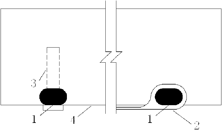
[0043] like figure 2 As shown, additional rods with holes are installed using rod-shaped inserts: For T-beams, box girders or rectangular beams that are not allowed to penetrate the flange, the longitudinal rods around which the U-shaped fiber sheets can be installed Angular parts. The horizontal rods for the longitudinal fiber sheets for flexural reinforcement usually must be installed on the top, bottom or side of the beam (slab) because there is no place to press against. Use additional rods with anchor holes, use rod-shaped inserts such as screws and rivets to pass through the anchor holes on the additional rods and then insert them into the pre-prepared holes on the component for anchoring, so that the additional rods are installed on the corresponding position on the component (such as figure 2 shown on the left). In order to make the fiber sheets after winding the rod stacked without spacing (such as figure 2 As shown on the right), you can chisel grooves in advan...

Embodiment 3

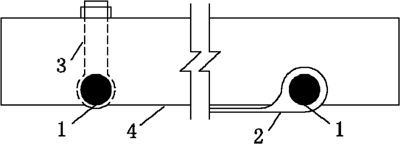
[0045] like image 3 , 4 As shown, the additional rods are installed with joint-shaped rods with holes: there are multiple joint-shaped rods with holes, and the holes of the joint-shaped rods with holes penetrate into the additional rods, and the joint-shaped rods with holes Scattered arrangement, requiring that the clear distance between two adjacent joint-shaped rods with holes is not less than the width of the fiber strip, and the shaft of the joint-shaped rod with holes is inserted into the pre-prepared hole on the component for anchoring, so Install additional rods at corresponding positions on the member (such as image 3 , 4 shown on the left). In order to make the fiber sheets after winding the rod stacked without spacing (such as image 3 , 4 As shown on the right), you can chisel grooves in advance where additional rods are required, and then glue the additional rods into place. image 3 The upper end of the joint-shaped rod with a hole is anchored by a nut. T...


PUM


Abstract

The invention discloses a method for lapping and anchoring a fiber sheet around rod to reinforce a structural component, wherein two hard rod members are used, and the length direction of the rod member is vertical to that of a band-shaped fiber sheet; the method comprises the following steps: 1, pre-pressing or mounting the rod member on a reinforced structural component, tightening the fiber sheet around the rod member, lapping the two end parts of the fiber sheet in an adhesive or welded manner, and finishing the reinforcement of the structural component; 2, lapping the two end parts of the fiber sheet, respectively penetrating the two rod members into the lapped fiber sheet, mounting on the reinforced structural component after tightening, and finishing the reinforcement of the structural component. The method for lapping and anchoring a fiber sheet around rod to reinforce a structural component has simple operation and remarkable effect.

Description

technical field [0001] The invention relates to an anchoring method for fiber sheets, in particular to a method for anchoring U-shaped fiber sheets on civil engineering structural components such as buildings and bridges for shearing reinforcement. technical background [0002] Due to various reasons, a large number of civil engineering structures such as houses and bridges need to be reinforced and repaired. Fiber sheets such as carbon fiber cloth are used for the reinforcement of concrete structural members. They have the advantages of light weight, high strength, corrosion resistance and easy construction, so they are very popular in relevant engineering practice. [0003] When viscose fiber cloth is used for shear reinforcement of concrete beams, according to the projected shape of the cloth on the cross-section of the beam, the pasting forms can be summarized as side pasting and U-shaped pasting ( figure 1 (a)) and the enclosing paste ( figure 1 (c)) and so on. The p...

Claims


Application Information

Patent Timeline
Patent Type & Authority Patents(China)
IPC IPC(8): E04G23/02E01D22/00E01D101/24
Inventor 周朝阳周欣涛周奥利
Owner CENT SOUTH UNIV
Learn More