Variable air inlet turbocharger structure

A turbocharger, a variable technology, applied in the direction of gas turbine devices, machines/engines, internal combustion piston engines, etc., can solve the problem of reducing the flow range of the compressor stage, etc., to reduce the flow, increase the flow, and expand the flow range Effect

Inactive Publication Date: 2010-12-29
JAPHL POWERTRAIN SYST
View PDF3 Cites 9 Cited by
  • Summary
  • Abstract
  • Description
  • Claims
  • Application Information

AI Technical Summary

Problems solved by technology

Vaned diffusers increase compressor stage efficiency but reduce the flow range over which the compressor stage can operate

Method used


Image

  • Variable air inlet turbocharger structure
  • Variable air inlet turbocharger structure
  • Variable air inlet turbocharger structure

Examples


Embodiment Construction

[0035] Below with reference to the accompanying drawings, through the description of the embodiments, the specific embodiments of the present invention, such as the shape, structure, mutual position and connection relationship between the various parts, the role and working principle of the various parts, etc., will be further described. Detailed instructions:

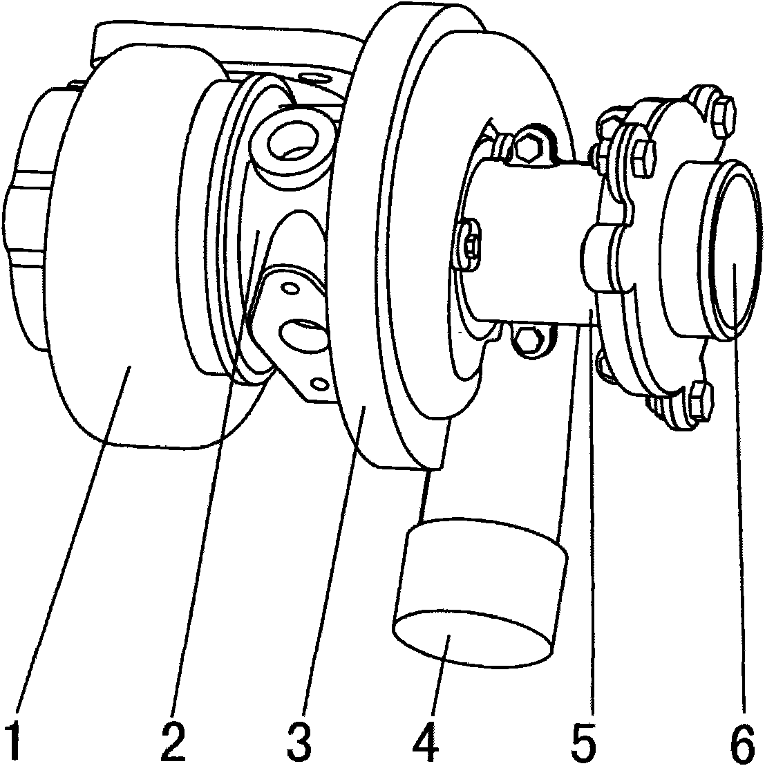
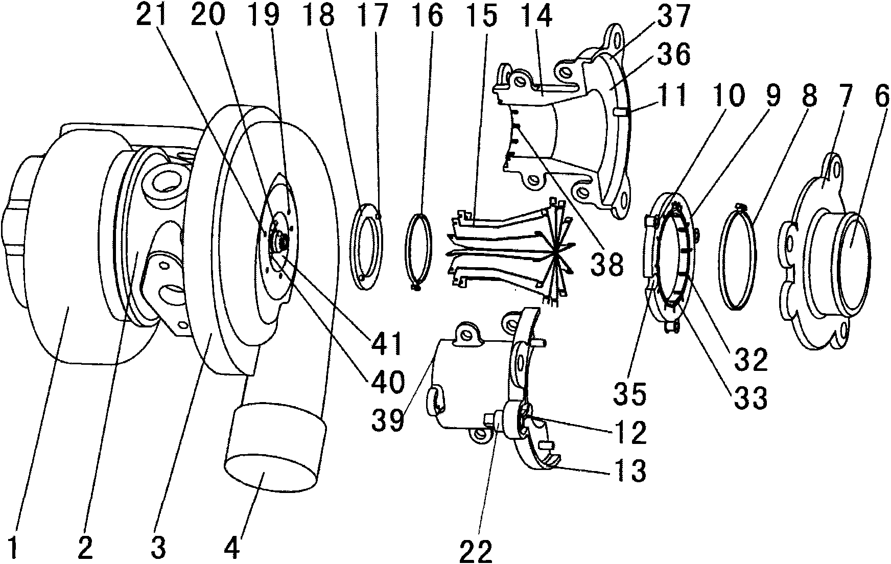
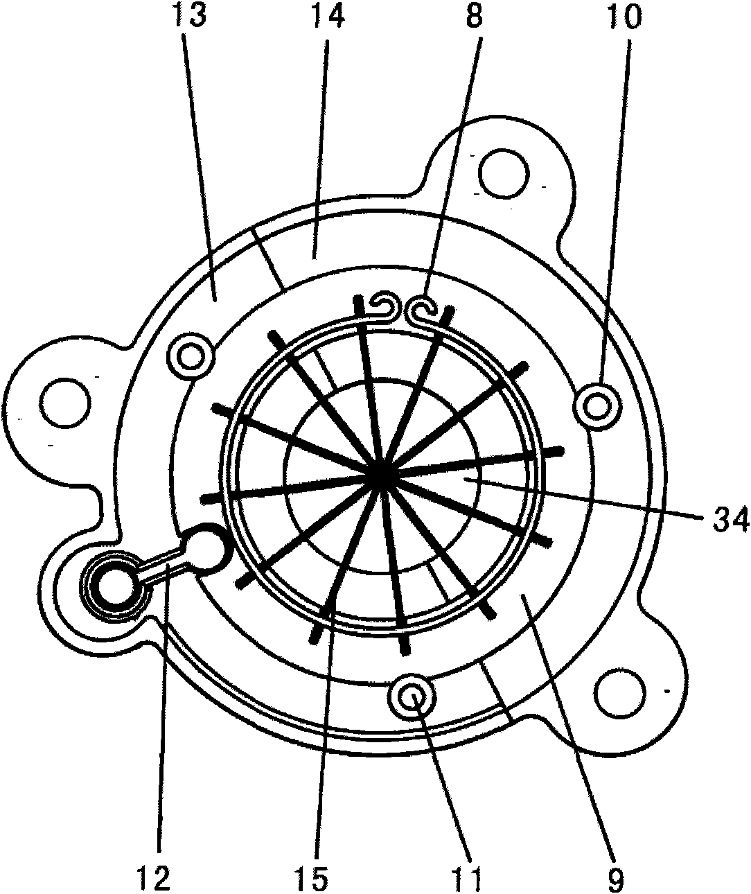
[0036] as attached figure 1 As shown, the present invention is a variable intake turbocharger structure, including a volute 1, an intermediate casing 2, and a pressure casing 3. The location of the pressure casing inlet 41 of the turbocharger structure can change the inlet pressure. The air intake adjustment device 5 in the airflow direction in the shell 3, the air intake adjustment device 5 includes a cavity 34 with a cavity structure, and more than one guide vane 44 with a sheet structure is arranged in the cavity 34. The air intake adjustment device 5 also includes a drive mechanism 49 that drives the guide vane 44...


PUM


Abstract

The invention provides a turbocharger structure which is applied in the technical field of a turbocharger and can change an air flow direction entering into a press shell. The variable air inlet structure turbocharger comprises a turbine shell (1), a middle shell (2) and the press shell (3); a press shell inlet (41) of the turbocharger structure is provided with an air inlet adjusting device (5) which is capable of changing the air flow direction entering into the press shell (3); the air inlet adjusting device (5) comprises a cavity (34) with a hollow structure; more than one sheet-shaped guide blade (44) is installed in the cavity (34); the air inlet adjusting device (5) further comprises a driving mechanism (49) for driving the guide blade (44) to torque. The technical scheme of the invention can change the air flow direction in the inlet of the gas compressor, efficiently reduce the flow rate while surging, improve the flow rate while blocking, widen the flow rate range of the turbocharger and improve the efficiency and pressure ratio of the turbocharger.

Description

technical field [0001] The invention relates to the technical field of turbocharging, and more specifically relates to a turbocharger structure capable of changing the direction of air flow entering the pressure shell. Background technique [0002] Turbochargers are widely used in the field of internal combustion engines. The high-temperature, high-pressure, high-energy exhaust gas discharged from the internal combustion engine drives the turbine of the turbocharger turbine stage to rotate, and the turbine drives the impeller of the compressor stage coaxial with it to rotate. The high-speed rotating compressor The impeller compresses the air from the air filter, and the pressurized air flows to the engine intake manifold and engine cylinders. Cars with turbochargers, especially passenger cars running in cities, have a large range of engine load changes, which requires that the compressor stage of the turbocharger can operate in a wide range of flow and meet the requirements ...

Claims


Application Information

Patent Timeline
Patent Type & Authority Applications(China)
IPC IPC(8): F02B37/24F02C6/12
CPCY02T10/144Y02T10/12
Inventor 施法佳范礼项青新
Owner JAPHL POWERTRAIN SYST
Why Eureka
Try Eureka