Flowmeter for laminar flow
A laminar flow flowmeter and pressure tube technology, which is used in the detection of fluid flow by measuring differential pressure, volume/mass flow generated by mechanical effects, etc. High problems, to achieve the effect of low production cost, reduced production cost and high measurement accuracy
- Summary
- Abstract
- Description
- Claims
- Application Information
AI Technical Summary
Problems solved by technology
Method used
Image
Examples
Embodiment 1
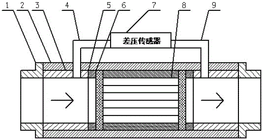
[0023] The main body 2 adopts a hollow cylinder structure with a wall thickness of 25mm and a length of 100mm, and a square through hole with a size of 15*15mm. There are two pressure introduction holes in the axial direction of the main body 2, which communicate with the through holes on the main body 2, respectively located on both sides of the laminar flow element 8, and the diameter of the holes is 3 mm. The main body 2 can be made of materials such as stainless steel, aluminum alloy or plastic.
[0024] The upstream pressure introduction pipe 4 and the downstream pressure introduction pipe 9 are respectively fixed on the two pressure introduction holes, and the fixing method can be threaded connection or welding. The upstream pressure induction pipe 4 and the downstream pressure induction pipe 9 can be made of materials such as stainless steel. The upstream pressure introduction pipe 4 and the downstream pressure introduction pipe 9 are respectively connected with the hi...
Embodiment 2
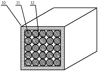
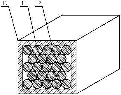
[0035] In the laminar flow meter designed in the present invention, the discharge method of the solid round rods 11 in the laminar flow element 8 can also be closely arranged in a fork row, and the specific scheme refers to the method in the first embodiment. Compared with the first embodiment, the laminar flow meter designed by the technical scheme adopted in this embodiment has a more stable laminar flow, higher measurement accuracy, and can adapt to a wider flow range.
Embodiment 3
[0037] In the laminar flowmeter designed in the present invention, the laminar flow element 8 can be made of a solid round rod 11 with a diameter of 3 mm. For a specific solution, refer to the method of using a solid round rod 11 with a diameter of 1 mm to make a laminar flow element. Compared with the first embodiment, the laminar flow meter designed in this embodiment has poorer laminar flow stability and a slightly lower applicable flow range, but the manufacturing cost is lower.
PUM
| Property | Measurement | Unit |
|---|---|---|
| Wall thickness | aaaaa | aaaaa |
| Length | aaaaa | aaaaa |
Abstract
Description
Claims
Application Information
 - R&D
- Intellectual Property
- Life Sciences
- Materials
- Tech Scout
- Unparalleled Data Quality
- Higher Quality Content
- 60% Fewer Hallucinations
Browse by: Latest US Patents, China's latest patents, Technical Efficacy Thesaurus, Application Domain, Technology Topic, Popular Technical Reports.
© 2025 PatSnap. All rights reserved.Legal|Privacy policy|Modern Slavery Act Transparency Statement|Sitemap|About US| Contact US: help@patsnap.com


