Supercharge Your Innovation With Domain-Expert AI Agents!

Method and device for diagnosing a position encoder

A transmitter and position adjustment technology, which is applied in the direction of the charging system, engine components, engine control, etc., can solve the problems of adjusting the wrong orientation of the transmitter, mismatching cable bundles, and wrong feedback signals, etc.

Inactive Publication Date: 2010-12-29
ROBERT BOSCH GMBH
View PDF2 Cites 6 Cited by
  • Summary
  • Abstract
  • Description
  • Claims
  • Application Information

AI Technical Summary

Problems solved by technology

[0004] Especially in the early stages of development where the electrical connections of the entire system are not fully or partially made with anti-reverse plug connectors, mismatched cable harnesses, misconfigured software adjacent to the hardware, or wrong pin configurations can lead to misconnection of the connecting wires , resulting in incorrect orientation of the triggering of the adjustment transmitter and / or incorrect feedback signals from the adjustment transmitter sensor mounted on the adjustment transmitter
If the adjustment transmitter motor connection is wrong and / or the adjustment transmitter sensor connection is wrong, in some cases this may cause such consequences: When professionals are looking for a fault, if the position feedback signal of the adjustment transmitter sensor is used Simple plausibility checks by tweaking transmitter functions can be misleading and thus labor-intensive to find faults

Method used


Image

  • Method and device for diagnosing a position encoder
  • Method and device for diagnosing a position encoder
  • Method and device for diagnosing a position encoder

Examples


Embodiment Construction

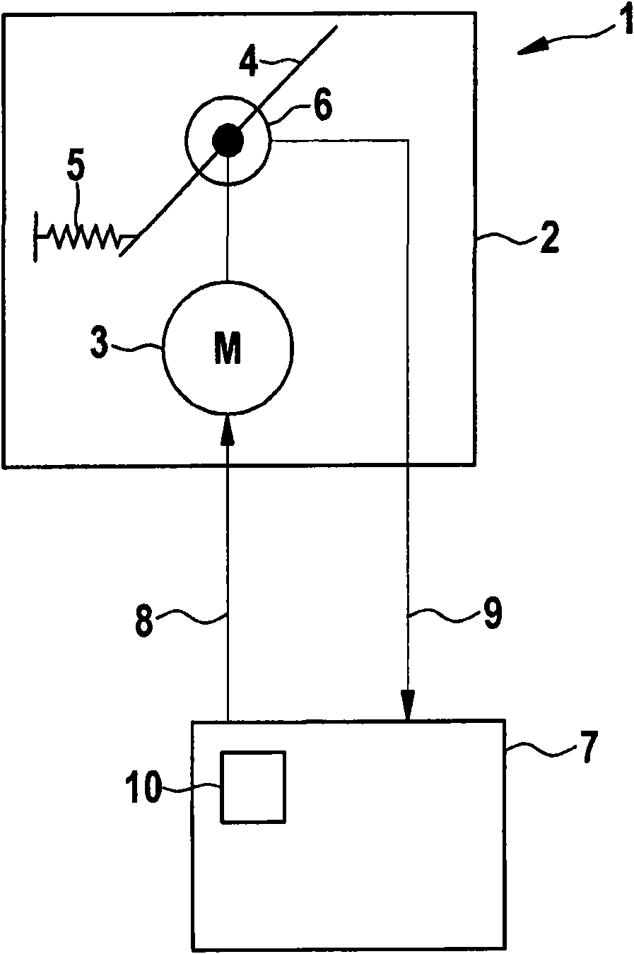
[0031] attached figure 1 Shown is a control transmitter system 1 with a control transmitter 2 , which is used, for example, in an internal combustion engine of a motor vehicle. Adjustment transmitter 2 corresponds, for example, to a throttle valve of an air system, an exhaust gas recirculation valve, a blow-off valve of an exhaust gas turbocharger or another variably actuatable adjustment transmitter. The adjustment transmitter 2 can be activated electrically, and the position of the adjustment transmitter or the position of one or more actuators 4 can be adjusted according to the activation parameters.

[0032] attached figure 1 The illustrated adjusting transmitter 2 includes an adjusting transmitter motor 3 in the form of a DC motor. The DC motor is triggered through the trigger line 8 . The DC motor is expediently used in combination with an actuator 4 , for example a valve or throttle of the air system, or another type of actuator. The actuator 4 can change its adjust...


PUM


Abstract

The invention relates to a method and a device for diagnosing a position encoder. The position encoder comprises a position encoder motor controlled by a plurality of terminals so that a mixup of at least two of the terminals of the position encoder motor leads to a reversal of the actuating direction of the position encoder, having the following steps: setting an actuating element of the position encoder to a zero setting (N), from which a motion of the actuating element is possible in one or two directions; controlling the position encoder motor according to a diagnostic variable, which is selected so that, in the case of a non-mixup of the terminals and in the case of a mixup of the terminals, different values of the changes are to be expected in the changes of the actuation position of the actuating element; detecting a change in the actuation position of the actuating element that comes about by the controlling of the position encoder motor; establishing a mixup of at least two of the terminals, if the value of the current change of the actuation position of the actuating element (4) deviates from the value of the change in the actuation position that is to be expected.

Description

technical field [0001] The invention relates to an engine system with a steering transmitter which can be activated electrically via a control unit. The adjustment position of the adjustment transmitter can be detected by one or more suitable adjustment transmission sensors, and fed back to the control unit to check the rationality of the required adjustment position. Background technique [0002] In engine systems equipped with internal combustion engines a series of electrically activated adjustment transmitters is usually used, the adjustment position of which is detected by suitable sensors so that their corresponding adjustment position can be checked when the relevant adjustment transmitter is activated. Examples of suitable adjustment transmitters of this type are, for example, throttle valves in the intake system of the relevant internal combustion engine, exhaust gas recirculation valves, blow-off valves for controlling turbochargers, etc. [0003] Usually a direct...

Claims


Application Information

Patent Timeline
Patent Type & Authority Applications(China)
IPC IPC(8): F02D9/08F02M25/07F02B37/18F02D41/22
CPCF02B37/18F02D9/105F02D2011/102F02D2200/0404F02D41/22F02D2250/16F02D2400/22Y02T10/40F02D41/0077F02M25/0756F02D41/0002F02M26/48
Inventor Z·托森T·鲍曼R·比尔G·舒马彻尔C·韦特泽尔
Owner ROBERT BOSCH GMBH
Features
  • R&D
  • Intellectual Property
  • Life Sciences
  • Materials
  • Tech Scout
  • Unparalleled Data Quality
  • Higher Quality Content
  • 60% Fewer Hallucinations
Learn More