Pressure type air flotation separation device

An air flotation separation and pressure technology, which is applied in liquid separation, separation methods, grease/oily substance/float removal devices, etc. Oil-water separation efficiency and other issues, to avoid the leakage of harmful gases, improve the oil-water separation effect, and stabilize the oil-water separation interface

Active Publication Date: 2011-01-05
浙江海牛海洋工程有限公司
View PDF5 Cites 9 Cited by
  • Summary
  • Abstract
  • Description
  • Claims
  • Application Information

AI Technical Summary

Problems solved by technology

[0005] However, the existing air-dissolved water release device mainly forms a high-speed air-dissolved water fluid in the form of a shrinking tube jet. During this process, the gas rapidly expands and floats up, which increases the instability of the fluid flow and easily leads to the separation of oil and water. Back mixing occurs, reducing oil-water separation efficiency
In addition, because the dissolved air water releaser is prone to blockage, it needs to be cleaned irregularly, and sometimes the whole machine needs to be stopped for inspection, so the workload of maintenance and repair is heavy, which affects production efficiency

Method used


Image

  • Pressure type air flotation separation device
  • Pressure type air flotation separation device
  • Pressure type air flotation separation device

Examples


Embodiment 1

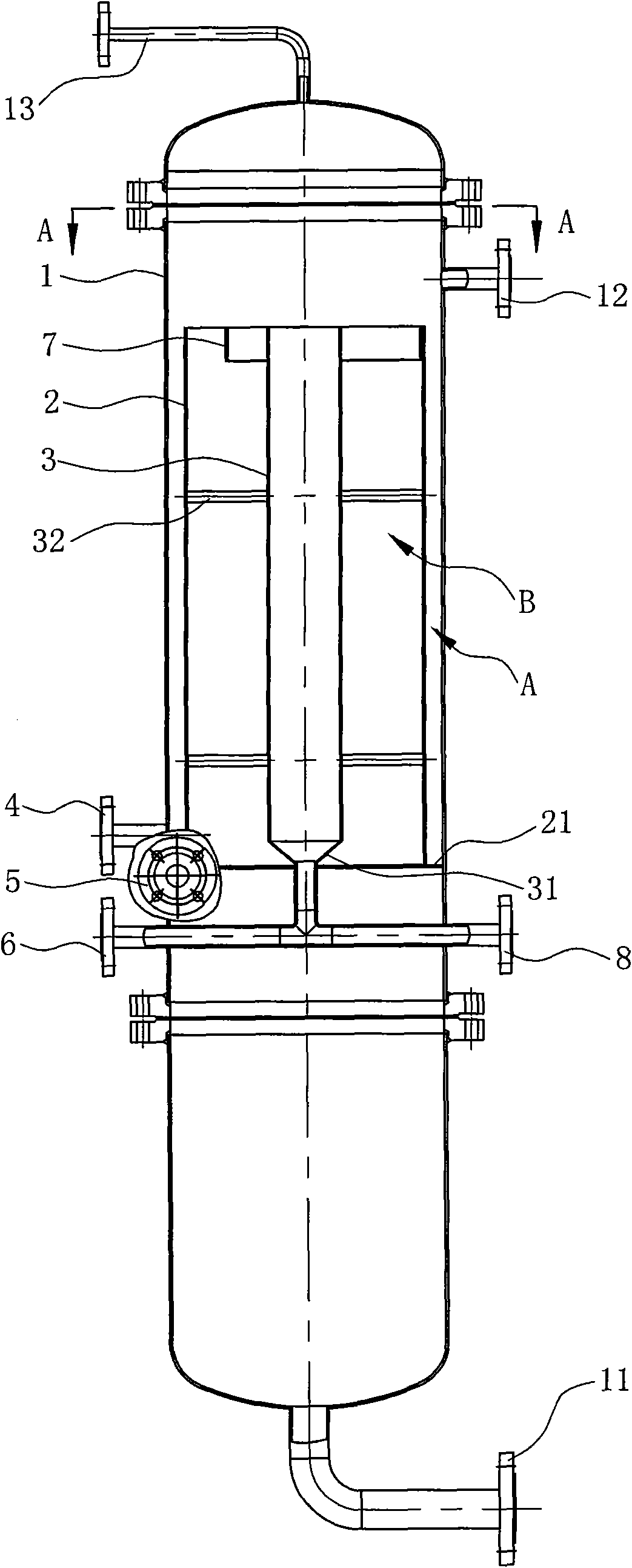
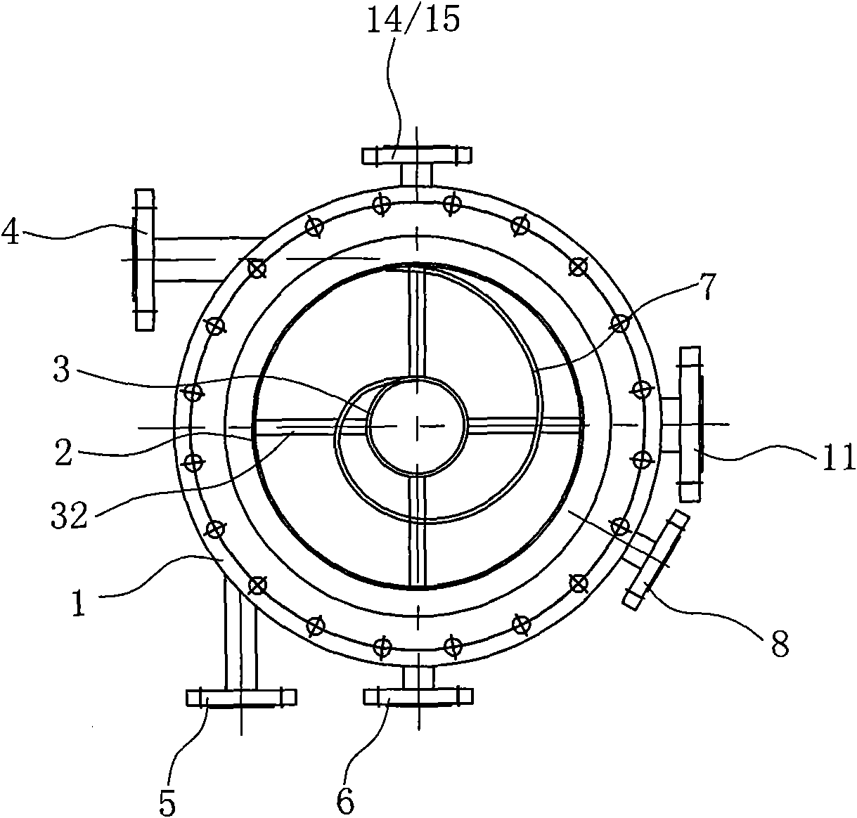
[0034] Such as figure 1 , figure 2 As shown, the pressure type air flotation separation device includes a tank body 1, a bubble rectifier 2 and an oil receiver 3 arranged in the tank body 1;

[0035] Wherein, the oil receiver 3 is a cylindrical cylinder with a funnel-shaped bottom 31, fixed to the air flotation rectifier 2 by two sets of divergent and evenly distributed fixing rods 32 arranged on the periphery of the oil receiver 3, The bubble rectifier 2 is sleeved outside the oil receiver 3, and an annular bottom plate 21 is arranged between the bottom of the bubble rectifier 2 and the inner wall of the tank body 1, so that the bubble rectifier 2 and the tank body 1 are fixed and the oil is collected. The cylinder 3 and the bubble rectifier cylinder 2 are fixed relative to the tank body 1 and arranged coaxially with the tank body 1;

[0036] A bubble rectifying area A with a closed bottom is formed between the outer wall of the bubble rectifying cylinder 2 and the inner w...

Embodiment 2

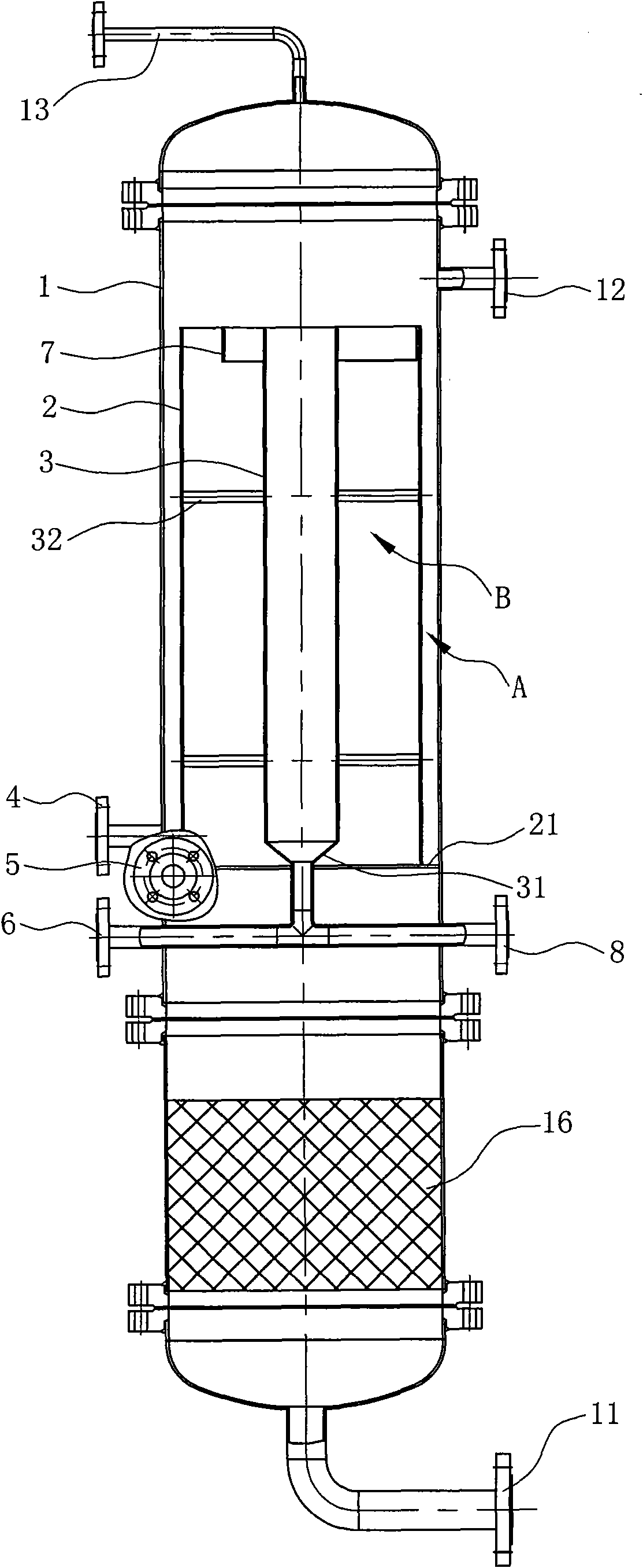
[0047] Such as image 3 As shown, the difference between the second embodiment of the present invention and the first embodiment is that a packing layer 16 is arranged in the tank body 1 below the air bubble rectifier 2, and the oil droplets are captured by the entrapment and adsorption effect of the packing layer 16. , which greatly simplifies the oil removal process and can complete the intensive treatment of oily water.


PUM


Abstract

The invention discloses a pressure type air flotation separation device, which comprises a tank body (1), and an oil collecting barrel (3) and an air bubble flow rectifying barrel (2) which are arranged in the tank body (1), wherein an air bubble flow rectifying area (A) of which the bottom is sealed is formed between the outer side wall of the air bubble flow rectifying barrel (2) and the inner side wall of the tank body (1); a flotation separation area (B) of which the bottom is open is formed between the inner side wall of the air bubble flow rectifying barrel (2) and the outer side wall of the oil collecting barrel (3); an oil-containing water inlet pipe (4) and a gas-dissolving water inlet pipe (5) are arranged on the tank body (1) tangentially; and a water discharge pipe (11) is arranged at the bottom of the tank body (1). Compared with the prior art, the pressure type air flotation separation device has the advantages that: the interference of large air bubbles with the oil-water flotation separation area is avoided, the oil-water separation interface is more stable and the separation efficiency is high; mutual fusion of micro air bubbles is inhibited, so that the success rate of the contact and adhesion between the micro air bubbles and oil drops with small particle sizes is improved considerably; and thus, the oil-water separation effect is improved considerably. In addition, the device adopts a sealed tank body, so harmful gases are prevented from leaking to the outside.

Description

technical field [0001] The invention relates to the technical field of oil-water separation treatment on offshore platforms, land oil fields, etc., in particular to a pressure type air flotation separation device for separating oil and water under pressure conditions and using air flotation. Background technique [0002] In the process of generation, transportation and storage of oil and natural gas, the main natural companion is water. In order to make the oily water in oil fields with different water quality characteristics meet the reinjection or discharge standards, according to the current mainstream oily water treatment process, it can be roughly divided into: gravity oil recovery, sedimentation, filtration process; pressure coalescence sedimentation separation, filtration process Three basic oily water treatment modes, including flotation degreasing purification and filtration process. [0003] As the main oily water degreasing equipment in the flotation process, mos...

Claims


Application Information

Patent Timeline
Patent Type & Authority Applications(China)
IPC IPC(8): C02F1/24C02F1/40
Inventor 马立峰樊燕王守波
Owner 浙江海牛海洋工程有限公司
Why Eureka
Try Eureka