Weft selector and weft selecting device
A weft selector and weft selection technology, which is applied in textiles, textiles, papermaking, looms, etc., can solve the problems of slow motion speed, complex structure, and large volume, and achieve fast reciprocating motion, simple structure, and small volume. Effect
- Summary
- Abstract
- Description
- Claims
- Application Information
AI Technical Summary
Problems solved by technology
Method used
Image

Examples
Embodiment 1
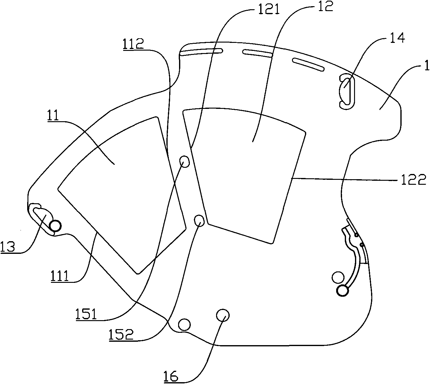
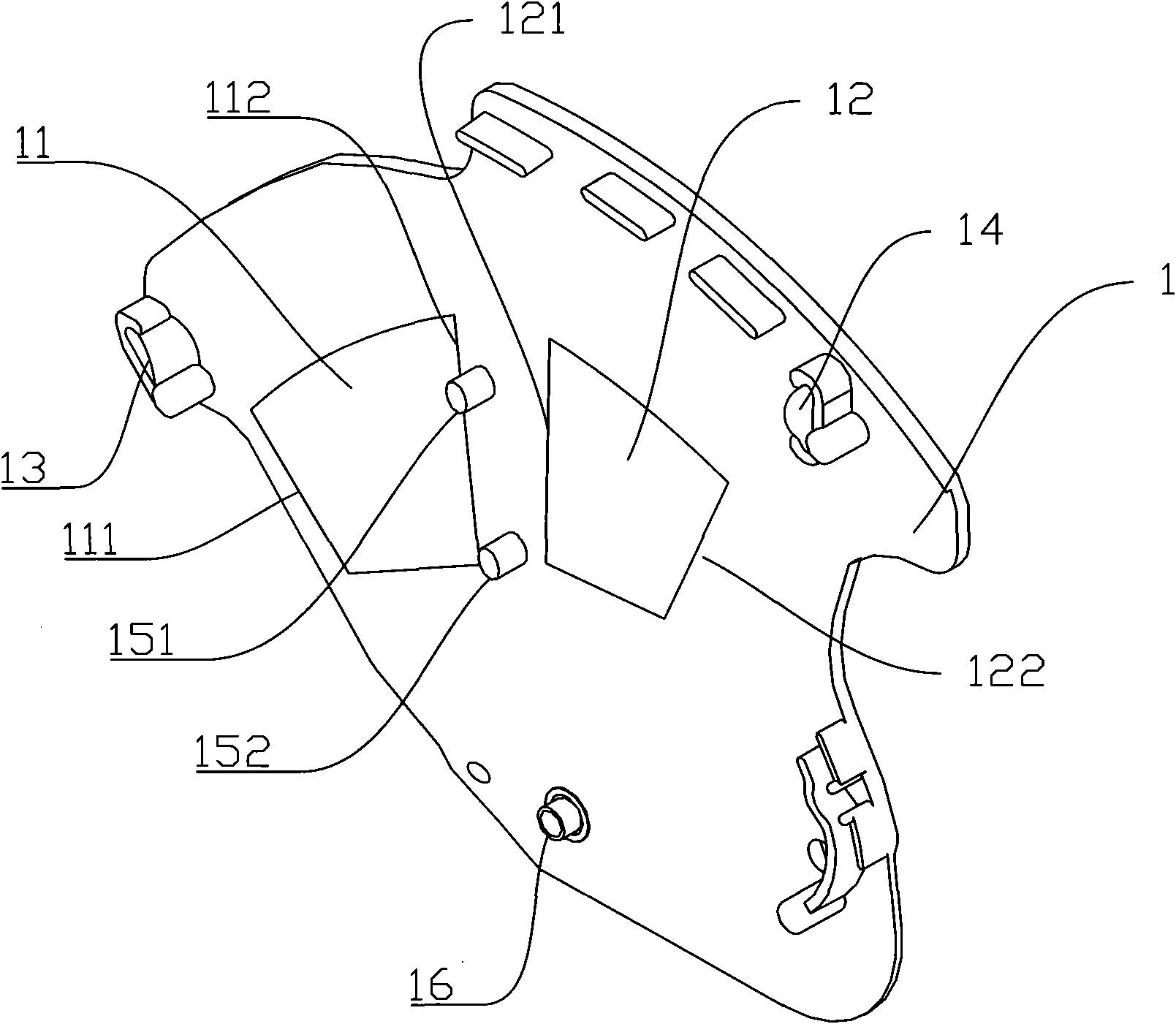
[0041] weft selector, such as figure 1 with figure 2 As shown, the permanent magnet sheet 1 is included. The permanent magnet sheet 1 is a thin sheet with a thickness of 3-5mm. Its specific thickness can be determined according to load-bearing requirements. The permanent magnet piece 1 is embedded with a first permanent magnet block 11 and a second permanent magnet block 12 . The first permanent magnet block 11 has a first pole 111 and a second pole 112 . The polarity of the first pole 111 and the second pole 112 are opposite. figure 1 Taking the counterclockwise direction as standard, the first pole 111 is located in front of the second pole 112 .
[0042] The permanent magnet piece 1 is also embedded with a second permanent magnet block 12 . The second permanent magnet block 12 has a third pole 121 and a fourth pole 122 . The third pole 121 is opposite in polarity to the fourth pole 122 . Based on the counterclockwise direction, the first permanent magnet block 11 i...
Embodiment 2
[0056] Such as Figure 7 As shown, the difference between Embodiment 2 and Embodiment 1 lies in that only the first permanent magnet block 11 is provided on the permanent magnet sheet 1 , and the second permanent magnet block 12 is not provided. All the other structures and methods of use are the same as in Example 1.
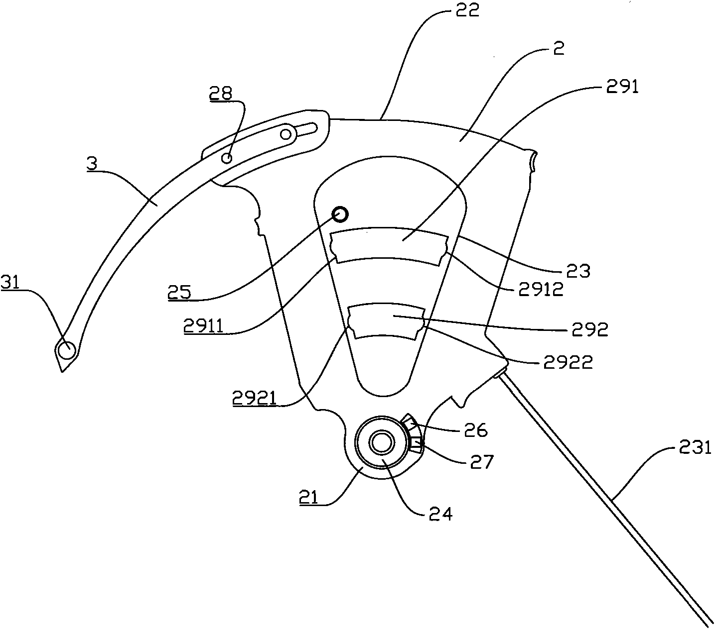
[0057] Such as Figure 7 As shown, in the first use state, the electromagnetic sheet 2 is in contact with the second block 14 . When there is a current in the first direction in the coil 23, the first pole 111 attracts the coil 23, and the second pole 112 repels the coil 23, so that the electromagnetic sheet 2 rotates counterclockwise until the electromagnetic sheet 2 is blocked by the first block 13 and cannot continue turn. Such as Figure 8 Shown is the second use state of this embodiment. At this time, if the current in the second direction opposite to the first direction passes through the coil 23, the first pole 111 repels the coil 23, and the second ...
Embodiment 3
[0059] Such as Figure 9 As shown, the difference between Embodiment 3 and Embodiment 1 is that only the second permanent magnet block 12 is provided on the permanent magnet sheet 1 , and the first permanent magnet block 11 is not provided. All the other structures and methods of use are the same as in Example 1.
[0060] Such as Figure 10 As shown, in the first use state, the electromagnetic sheet 2 is in contact with the second block 14 . When there is current in the coil 23 in the first direction, the third pole 121 repels the coil 23, and the fourth pole 122 attracts the coil 23. In this embodiment, it can be set so that the repulsion force of the third pole 121 to the coil 23 is greater than that of the fourth pole 122 to the coil 23 Appeal. Due to the blocking of the second block 14, the electromagnetic sheet 2 cannot rotate clockwise. Therefore, the electromagnetic sheet 2 can only rotate counterclockwise. The electromagnetic sheet 2 rotates counterclockwise until...
PUM
 Abstract
Description
Claims
Application Information
 - R&D Engineer
- R&D Manager
- IP Professional
- Industry Leading Data Capabilities
- Powerful AI technology
- Patent DNA Extraction
Browse by: Latest US Patents, China's latest patents, Technical Efficacy Thesaurus, Application Domain, Technology Topic.
© 2024 PatSnap. All rights reserved.Legal|Privacy policy|Modern Slavery Act Transparency Statement|Sitemap