Cam oil-supply type electro-hydraulic valve driving system

A drive system and fuel supply technology, applied in the direction of engine components, machines/engines, and non-mechanically actuated valves, can solve the problems of low valve flexibility and inability to realize the secondary opening of exhaust valves, etc., to achieve The effect of reducing energy consumption

Inactive Publication Date: 2011-01-05
DALIAN UNIV OF TECH
View PDF6 Cites 20 Cited by
  • Summary
  • Abstract
  • Description
  • Claims
  • Application Information

AI Technical Summary

Problems solved by technology

This system eliminates the restriction of the valve driving process by canceling the common rail pipe structure, but most of its research is in the initial stage, and has the disadvantages of low valve variable flexibility and inability to realize the second opening event of the exhaust valve.

Method used


Image

  • Cam oil-supply type electro-hydraulic valve driving system
  • Cam oil-supply type electro-hydraulic valve driving system
  • Cam oil-supply type electro-hydraulic valve driving system

Examples


Embodiment Construction

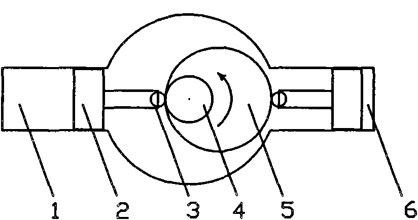
[0015] figure 1 A structure of an opposed cam-plunger oiler is shown. Since each cylinder of a four-stroke engine is always carried out in the order of intake, compression, work, and exhaust, the order of each cylinder's intake and exhaust is consistent with the ignition sequence of the engine. The opposed cam-plunger oiler is designed according to the number of cylinders and firing order of the engine. The oil feeder mainly includes a forward oil supply oil chamber 1, two oil supply plungers 2, two rollers 3, an oil supply camshaft 4, an oil supply cam 5 and a reverse oil supply oil chamber 6. As the oil supply camshaft 4 rotates, the oil supply cam 5 pushes the oil supply plunger 2 to move up and down, so that the forward oil supply oil chamber 1 and the reverse oil supply oil chamber 6 are alternately supplied with oil.

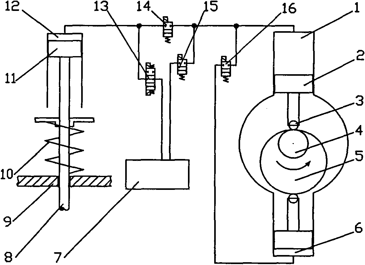
[0016] figure 2 A schematic diagram showing the working principle of the cam oil-fed electro-hydraulic valve actuation system for a single intake valv...


PUM


Abstract

The invention discloses a cam oil-supply type electro-hydraulic valve driving system and belongs to a variable-valve cam oil-supply type electro-hydraulic valve driving system of an engine. The cam oil-supply type electro-hydraulic valve driving system mainly comprises an oil supplier, a valve driving mechanism, an oil tank, a connection oil line and an electromagnetic valve. An opposed cam-plunger oil supplier is designed according to the number of cylinders of the engine and the ignition order, and hydraulic oil can be provided for all intake / exhaust valve driving mechanisms of the engine by using only two oil suppliers. A variable intake / exhaust valve can be realized and energy required by valve drive can be reduced by controlling a first electromagnetic valve between an oil supply oil cavity and a driving oil cavity. The secondary opening of the exhaust valve is realized by controlling a fifth electromagnetic valve. Energy consumption for charging the oil supply oil cavity can be reduced by matching a second electromagnetic valve between the oil supply cavity and the oil tank with a fourth electromagnetic valve between a forward oil supply oil cavity and a reverse oil supply oil cavity. When a third electromagnetic valve is used, a valve seat buffer and a valve gap regulator are saved, the valve closing speed is increased and the valve closing range is broadened.

Description

technical field [0001] The invention relates to a cam oil supply type electro-hydraulic valve drive system, which belongs to the cam oil supply type electro-hydraulic valve drive system capable of realizing variable valves of an engine. Background technique [0002] The variable valve technology can optimize the ventilation performance of the engine at different speeds, effectively reduce the fuel consumption of the engine, and improve its emission performance. In recent years, researchers at home and abroad have conducted a lot of in-depth research on variable valve technology, and developed a variety of variable valve systems, such as mechanical variable valve systems, electro-hydraulic variable valve systems, and electromagnetic variable valve systems. , Electric variable valve system, etc. Among them, the electro-hydraulic variable valve system is currently the most potential variable valve system. Most electro-hydraulic variable valve systems adopt a common rail oil s...

Claims


Application Information

Patent Timeline
Patent Type & Authority Applications(China)
IPC IPC(8): F01L9/02F01L9/10F01L9/40
Inventor 崔靖晨隆武强齐鲲鹏
Owner DALIAN UNIV OF TECH
Why Eureka
Try Eureka