High-pressure piston type accumulator

A technology of high-pressure pistons and accumulators, applied in the direction of mechanical equipment, etc., can solve the problems of pressure difference of seals, affecting the service life of seals, and reduction of pneumatic pressure, so as to achieve the effect of high operating pressure and prolonging service life

Inactive Publication Date: 2011-01-05
SHANGHAI HUIYI CONTROL SYST
View PDF0 Cites 20 Cited by
  • Summary
  • Abstract
  • Description
  • Claims
  • Application Information

AI Technical Summary

Problems solved by technology

[0004] The inner chamber of the cylinder of the traditional piston accumulator is divided into two working chambers by the piston, one of which is an oil chamber and the other is an air chamber. The pistons are equipped with seals and guide belts. Due to the frequent movements of the pistons During the process, the pressure oil will continue to accumulate on the side of the seal facing the oil chamber, which will cause a pressure difference on the seal when the piston moves, thereby affecting the service life of the seal. Similarly, the gas will gradually accumulate on the seal toward the gas chamber. On one side of the cavity, as the pressure increases, the gas will penetrate into the oil, which will lead to a gradual decrease in the pneumatic pressure, which will eventually fail to meet the function of the accumulator
Therefore, traditional piston accumulators can only be used in low-pressure systems (less than 10MPa), and have the disadvantage of poor system sealing performance

Method used


Image

  • High-pressure piston type accumulator
  • High-pressure piston type accumulator

Examples


Embodiment Construction

[0017] The embodiments of the present invention will be described in further detail below in conjunction with the accompanying drawings, but the present embodiments are not intended to limit the present invention, and any similar structures and similar changes of the present invention should be included in the protection scope of the present invention.

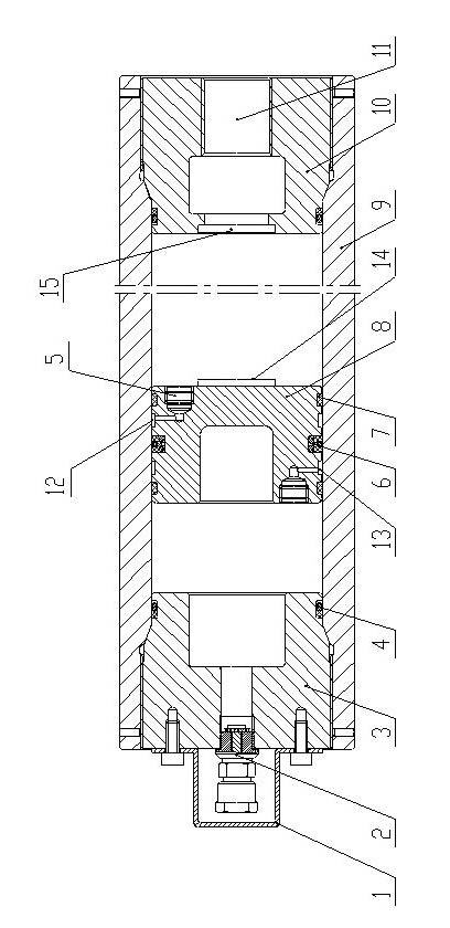
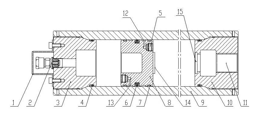
[0018] Such as figure 1 As shown, a high-pressure piston accumulator provided by the embodiment of the present invention includes a cylinder 9, a piston 8, an oil-side connecting flange 10 and an air-side connecting flange 3;

[0019] The cylinder 9 is provided with a cylindrical hollow cavity, the oil-side connecting flange 10 and the gas-side connecting flange 3 are respectively fixed on both ends of the cylinder 9 by threaded connection, and the oil-side connecting flange 10 and the gas-side The connecting flange 3 is coaxially provided with an annular sealing ring 4, and the outer ring surface of each annular sealing ring ...


PUM


Abstract

The invention discloses a high-pressure piston type accumulator, relating to the technical field of hydraulic auxiliary elements and solving the technical problem of prolonging the service life and enhancing the working pressure. The high-pressure piston type accumulator comprises a cylinder barrel, a piston arranged in the cylinder barrel, and an oil lateral connecting flange and a gas lateral connecting flange which are respectively fixed on the both ends of the cylinder barrel, wherein an oil hole is arranged on the oil lateral connecting flange; a charging nozzle is arranged on the gas lateral connecting flange; a circle of guide belt grooves, a circle of oil storage grooves, a circle of seal grooves, a circle of gas storage grooves and a circle of guide belt grooves are axially and successively arranged on the piton; guide belts are arranged in both two guide belt grooves; combined sealing elements are arranged in the seal grooves; a one-way valve is respectively arranged on the both ends of the piston; an inlet of one one-way valve is communicated with the gas storage grooves on the cylindrical surface of the piston, and an outlet of the one-way valve is communicated with an oil cavity; and an inlet of the other one-way valve is communicated with the gas storage grooves on the cylindrical surface of the piston, and an outlet of the one-way valve is communicated with a gas cavity. The accumulator can effectively avoid oil liquid from leaking into the gas.

Description

technical field [0001] The invention relates to the technology of hydraulic auxiliary components, in particular to the technology of a high-pressure piston accumulator. Background technique [0002] The piston accumulator has the advantages of simple structure, long life, small size, easy installation, easy maintenance, easy manufacture, etc. It is an indispensable auxiliary component in the hydraulic system. [0003] The piston accumulator mainly plays the following roles in the hydraulic system: 1) Absorb the pressure shock of the system, ease the system pressure and flow fluctuation; 2) Accumulate energy, supplement the flow when the pump displacement is insufficient; 3) Maintain pressure, It is used for pressure maintenance when the system is in a non-working cycle; 4) Safety function, it is used for the ability replenishment of the fast action of the actuator in the system. [0004] The inner chamber of the cylinder of the traditional piston accumulator is divided into...

Claims


Application Information

Patent Timeline
Patent Type & Authority Applications(China)
IPC IPC(8): F15B1/04
Inventor 陈建华万保中田贞明王伟晓
Owner SHANGHAI HUIYI CONTROL SYST
Why Eureka
Try Eureka