
Display panel and image correction method thereof

A display panel and image correction technology, applied in static indicators, cathode ray tube indicators, optics, etc., can solve the problems of light visual pollution, and there is no way to solve the problem of display unit wrapping and gaps cannot be eliminated

Inactive Publication Date: 2011-01-05
应骏
View PDF11 Cites 8 Cited by
  • Summary
  • Abstract
  • Description
  • Claims
  • Application Information

AI Technical Summary

Problems solved by technology

However, when this method is used, the following problems will be brought: due to the secondary refraction and reflection of light on the transparent protective plate and the lower surface, the image will have ghost images, and the surrounding ambient light will be incident from the surface of the protective plate into the inside causing Light and visual pollution; there is no way to solve the problem of wrapping (with border) of the display unit, especially when multiple display units are spliced ​​and displayed, the gap in the middle cannot be eliminated, which affects the visual effect

Method used


Image

  • Display panel and image correction method thereof
  • Display panel and image correction method thereof
  • Display panel and image correction method thereof

Examples


Embodiment 1

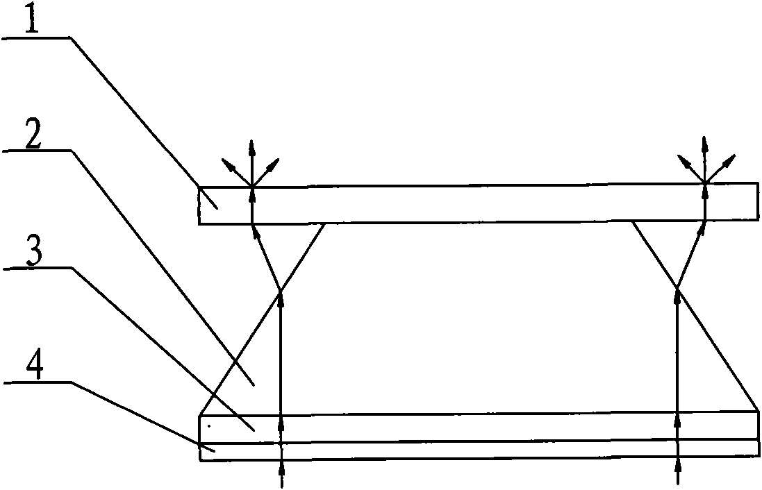
[0056] Such as figure 1 As shown, a display panel includes a light guide layer. The light guide layer includes a light-transmitting plate 2 and a bottom light-transmitting plate 3. The light-transmitting plate 2 and the bottom light-transmitting plate 3 are made of transparent materials. The refractive index of the two is the same or Similarly, the light-transmitting plate 3 is a rectangular truss structure with a small top and a large bottom. The lower surface of the light-transmitting plate 2 is connected with the bottom light-transmitting plate 3 through transparent glue or other viscous transparent materials. The lower surface of the light-transmitting plate 2 The surface size is the same as the upper surface of the bottom light-transmitting plate 3, and one or more layers of addition and subtraction films can be arranged on the upper and lower surfaces of the bottom light-transmission plate 3, and the addition and subtraction films are antireflection film, reflective film,...

Embodiment 2

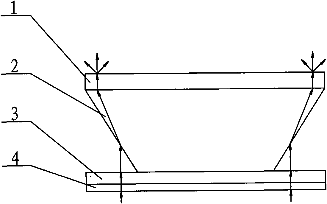
[0084] Such as figure 2 As shown, the light-transmitting plate 1 in the display panel is an inverted quadrangular truss structure with a large top and a small bottom, the size of the upper surface is the same as that of the bottom light-transmitting plate 3, and the rest of the structure in Embodiment 2 is basically similar to that of Embodiment 1. , which will not be described in this paper.

Embodiment 3

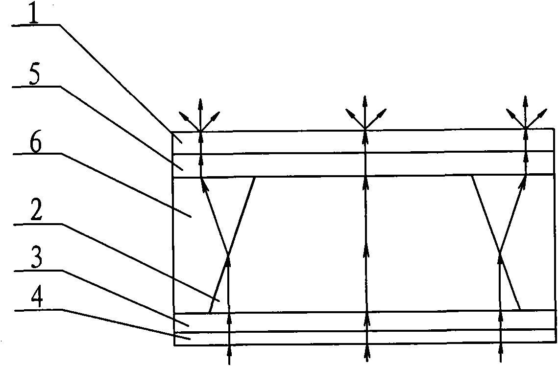
[0086] Such as image 3 As shown, the light guide layer of the display panel is composed of a surface light-transmitting plate 5, a light-transmitting plate 2, a side light-transmitting plate 6, and a bottom light-transmitting plate 3. The lower surface of the light plate 2 is smaller than the surface of the bottom light-transmitting plate 3, and the lower surface of the light-transmitting plate 2 is connected to the bottom light-transmitting plate 3 through transparent glue or other viscous transparent materials, and the upper surface of the light-transmitting plate 2 Also adopt transparent viscose or other viscous transparent materials to connect the surface light-transmitting plate 5, adopt the same method to connect four side light-transmitting plates 6 on the four sides of the light-transmitting plate 2, and the side light-transmitting plate 6 It consists of one or more layers of light-transmitting plates with different refractive indices. The light-transmitting plate 2 a...


PUM


Abstract

The invention relates to a display panel and an image correction method thereof, belonging to the technical field of image shift-forward display and amplification. The display panel comprises a light guiding layer, a scattering layer made of a one-side light permeating material is arranged on the upper surface of the light guiding layer in a matching way, and a light converging layer is arranged on the lower surface of the light guiding layer in a matching way. The light guiding layer comprises a hollow or solid light permeating plate with a quadrangular frustum pyramid or inverted quadrangular frustum pyramid structure, and the lower surface of the light permeating plate is provided with a bottom light permeating plate in a matching way. For the display panel and the image correction method thereof, the light guiding layer made of a transparent material is used for changing the light path, the lower surface of the light guiding layer is provided with the light converging layer, and thus, light rays are converged to be approximately parallel and then guided into the light guiding layer. The upper surface is provided with the scattering layer, and meanwhile, an image corrector is arranged to optimize and improve a displayed image. The display unit can be used for visually eliminating the gap between every two display units, and the integral effect of a screen picture is realized. The device has the characteristics of low production cost, convenient installation and stable quality and is applicable to large-scale popularization and utilization.

Description

technical field [0001] The invention belongs to the technical field of image forward display and magnification, and in particular relates to a display panel which can be applied to a common display unit for image forward movement and an image correction method for the display panel. Background technique [0002] CRT, LCD, PDP, DLP display units are more and more used in our daily work, due to their inherent physical characteristics (such as: framed, easy to crush, easy to scratch) in many applications limit its wider application. At present, to make up for the above-mentioned shortcomings, a method of adding a transparent protective plate in front of the display unit is adopted. However, when this method is used, the following problems will be brought: due to the secondary refraction and reflection of light on the transparent protective plate and the lower surface, the image will have ghost images, and the surrounding ambient light will be incident from the surface of the p...

Claims


Application Information

Patent Timeline
Patent Type & Authority Applications(China)
IPC IPC(8): G09F9/00G02B27/00G02B5/02G02B3/08G02B5/04G09G5/00
Inventor 应骏
Owner 应骏
Learn More