Optical signal generating and receiving methods and devices and optical transmission system

An optical signal and signal technology, applied in the field of communication, can solve problems such as difficult synchronization, blurring, decoding errors, etc., and achieve the effect of eliminating frequency asynchrony, simple implementation, and eliminating the problem of phase blurring.

Active Publication Date: 2014-02-19
HUAWEI TECH CO LTD
View PDF1 Cites 0 Cited by
  • Summary
  • Abstract
  • Description
  • Claims
  • Application Information

AI Technical Summary

Problems solved by technology

The receiver adopts the method of homodyne detection, so the local oscillator and the optical carrier at the sending end are required to be strictly synchronized, that is, frequency synchronization and phase synchronization, but it is difficult to achieve such strict synchronization in practice. Figure 1B In the phase estimator, it is necessary to use a complex algorithm to estimate the phase of the digital baseband signal, and average the estimated results in the averager, and the averager sends the obtained results to the decoder, and the digital Phase rotation of the baseband signal to eliminate the influence of the frequency difference and phase difference between the local oscillator and the optical carrier at the transmitting end
[0004] The inventor of the present invention found in the research process that there are at least the following problems in the prior art: although the optical receiver of the prior art can eliminate the frequency difference and phase difference between the local oscillator light and the optical carrier at the transmitting end through complex algorithms , but it cannot solve the phase ambiguity problem due to the phase modulation itself, resulting in errors during decoding

Method used


Image

  • Optical signal generating and receiving methods and devices and optical transmission system
  • Optical signal generating and receiving methods and devices and optical transmission system
  • Optical signal generating and receiving methods and devices and optical transmission system

Examples


Embodiment Construction

[0074] In order to facilitate those skilled in the art to understand and implement the present invention, the embodiments of the present invention are now described with reference to the accompanying drawings. Here, the exemplary embodiments of the present invention and the description thereof are used to explain the present invention, but not as a limitation to the present invention.

[0075] The technical solution of the present invention will be described below with reference to the drawings and embodiments.

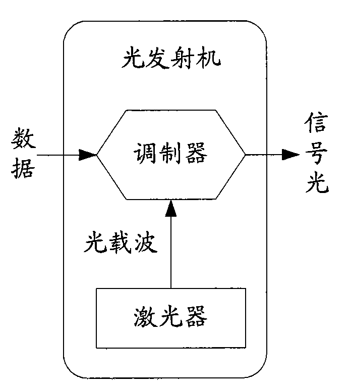
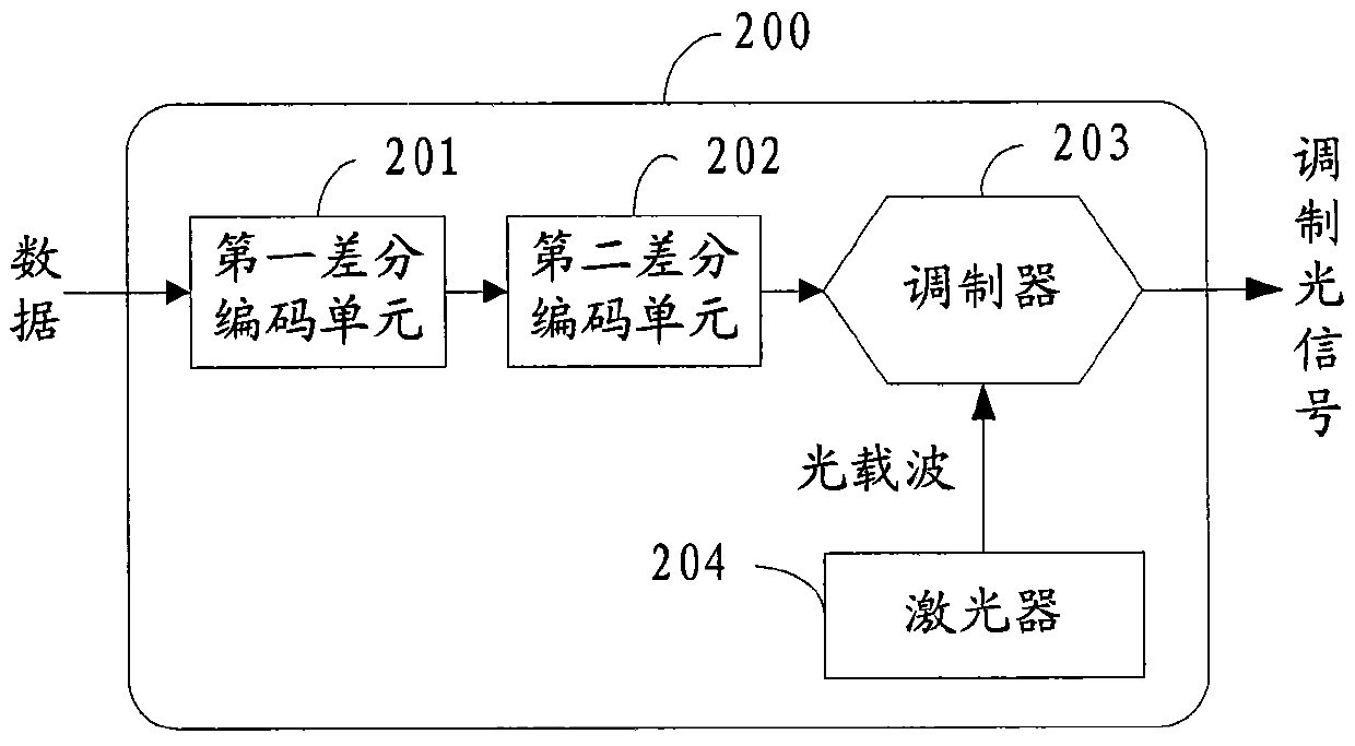
[0076] The embodiment of the present invention provides an optical signal generating device, the structure of which is as follows figure 2 As shown, it includes: a first differential encoding unit 201, a second differential encoding unit 202, and a modulator 203.

[0077] The first differential encoding unit 201 differentially encodes the data to obtain the first differential encoded data, and then uses the second differential encoding unit 202 to differentially encode the ...


PUM


Abstract

The embodiment of the invention relates to the field of communication and particularly discloses an optical signal generating method, an optical signal receiving method, an optical signal generating device, an optical signal receiving device and an optical transmission system. The optical signal generation method comprises: coding data in a differential manner to obtain first differentially coded data; coding the first differentially coded data in a differential manner to obtain second differentially coded data; and performing phase modulation on an optical carrier by using the second differentially coded data to obtain a modulation optical signal. With the optical signal generating method and the optical signal receiving method of the invention, a complex frequency offset control circuit and a phase estimation module are saved, but data transmitted by a transmitting end can be well restored from the modulation optical signal when a receiving end receives the modulation optical signal.

Description

Technical field [0001] The present invention relates to the field of communications, and in particular to a method, device and optical transmission system for generating and receiving optical signals. Background technique [0002] In recent years, due to the advantages of high sensitivity and good selectivity, coherent optical communication technology has been widely used in large-capacity and long-distance backbone networks. Coherent optical communication mainly uses coherent modulation and heterodyne detection technology. The so-called coherent modulation is to use the signal to be transmitted at the transmitting end to change the frequency, phase and amplitude of the coherent light to obtain signal light; the so-called heterodyne detection is to use the local oscillation light generated by the local oscillator light source and the signal light at the receiving end. Mixing is performed in the mixer to obtain an intermediate frequency signal that changes in the same law as the ...

Claims


Application Information

Patent Timeline
Patent Type & Authority Patents(China)
IPC IPC(8): H04L27/22H04L25/03H04B10/61H04B10/556
Inventor 黄远达解长松
Owner HUAWEI TECH CO LTD
Why Eureka
Try Eureka