Vehicle hydraulic drill

A hydraulic drilling rig and drilling rig technology, applied in the field of hydraulic drilling rigs, can solve the problems of time-consuming and laborious, difficult adjustment of the drilling direction of the hydraulic drilling rig, etc., and achieve the effect of increasing the feed stroke

Inactive Publication Date: 2011-01-12
SHANXI DONGHUA MACHINERY
View PDF7 Cites 10 Cited by
  • Summary
  • Abstract
  • Description
  • Claims
  • Application Information

AI Technical Summary

Problems solved by technology

[0002] At present, most coal mines need to temporarily install hydraulic drilling rigs when drilling underground. At this time, the underground boring machine stops working and retreats. The drilling direction is not easy to adjust, and it is necessary to manually move and adjust the direction of the drill pipe, which is time-consuming and laborious

Method used


Image

  • Vehicle hydraulic drill
  • Vehicle hydraulic drill
  • Vehicle hydraulic drill

Examples


Embodiment Construction

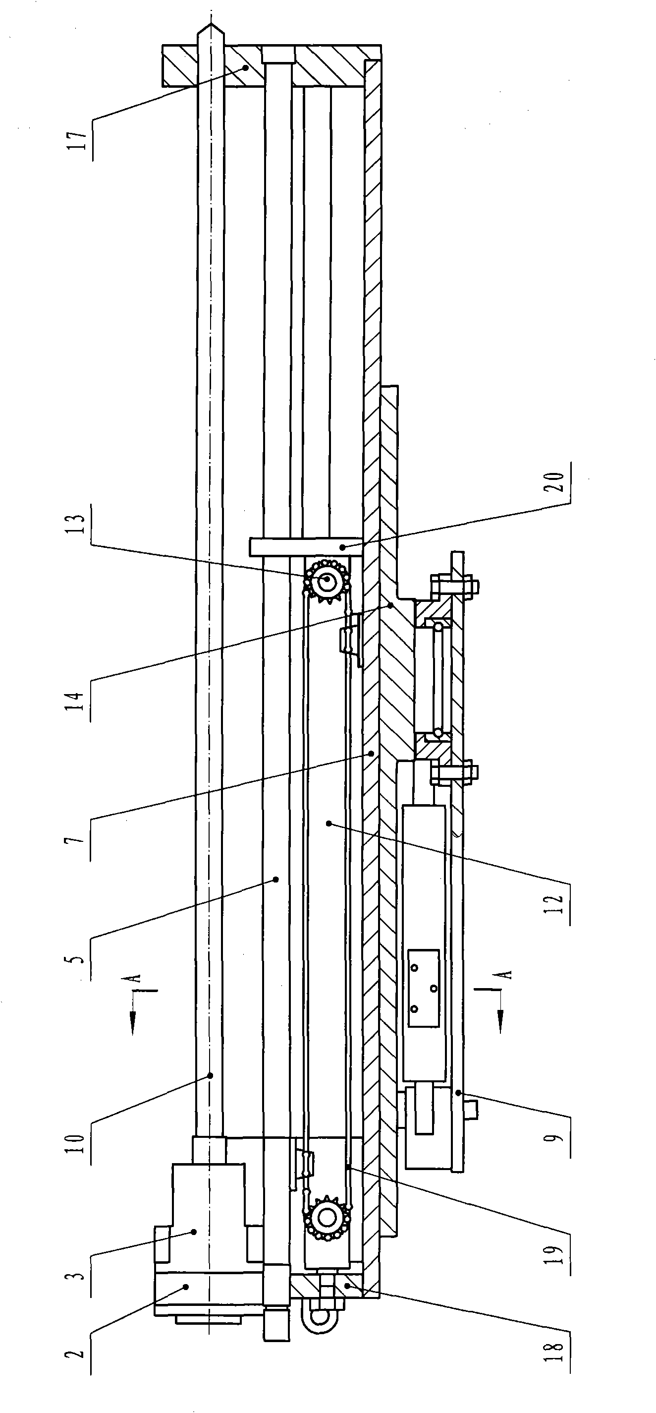
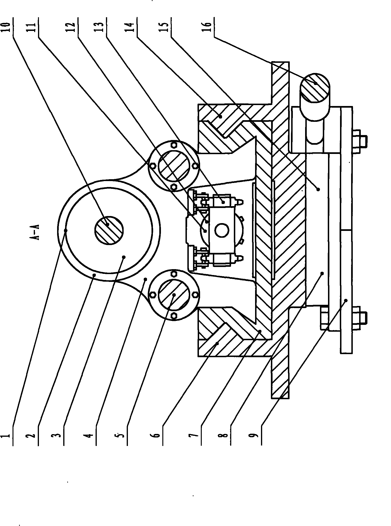
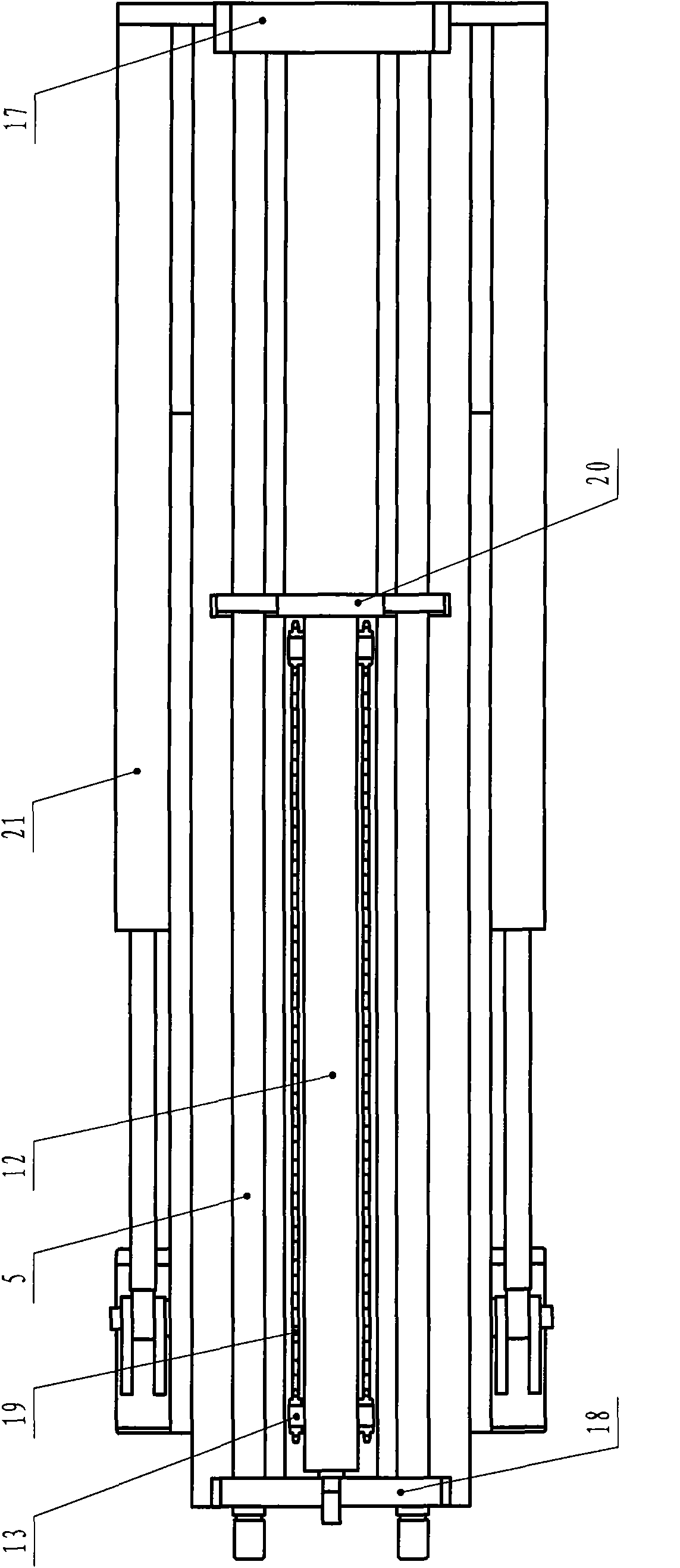
[0024] Such as figure 1 , figure 2 , image 3 , Figure 4 As shown, the airborne hydraulic drilling rig includes a rotary mechanism 8, a feed mechanism 11, a propulsion cylinder 21, a frame 6, a drilling machine component 1 and a base 9, the rotary mechanism 8 is arranged on the base 9, and the frame 6 is arranged on the rotary mechanism 8, the propulsion cylinders 21 are symmetrically arranged on both sides of the frame 6, the feed mechanism 11 is arranged in the frame 6, and the drilling rig components 1 are arranged on the frame 6;

[0025] Base 9 is fixed on the side of the boring machine cutting arm, the rear portion of the cutting head.

[0026] Frame 6 comprises slideway 14, dovetail-shaped carriage 7, slide bar 5, guide frame 17 and baffle plate 18, and slideway 14 is fixed on the rotating disk 15, and dovetail-shaped carriage 7 is arranged in the slideway 14, and dovetail-shaped slideway One end of the frame 7 is fixed with a guide frame 17, the other end is fixe...


PUM


Abstract

The invention relates to a vehicle hydraulic drill, which belongs to the technical field of hydraulic drills, and in particular relates to underground drilling equipment. The technical problem to be solved is to provide the vehicle hydraulic drill which does not need to be manually transported and can automatically adjust the direction and the position of a drill rod before drilling, thereby saving the installation time of the hydraulic drill and reducing the labor intensity of workers. The invention adopts the technical scheme that the vehicle hydraulic drill comprises a rotary mechanism, a feeding mechanism, propulsion cylinders, a stand, a drill part and a pedestal, wherein the rotary mechanism is arranged on the pedestal, the stand is arranged on the rotary mechanism, the propulsion cylinders are symmetrically arranged at both sides of the stand, the feeding mechanism is arranged in the stand, the drill part is arranged on the stand, and the pedestal is fixed on the lateral surface of the cutting arm of a digging machine and at the rear part of a cutting head; and the invention is applied to the technical flied of underground hydraulic drills.

Description

technical field [0001] The invention relates to an airborne hydraulic drilling rig, which belongs to the technical field of hydraulic drilling rigs. Background technique [0002] At present, most coal mines need to temporarily install hydraulic drilling rigs when drilling underground. At this time, the underground roadheader stops working and retreats. The drilling direction is not easy to adjust, and it is necessary to manually move and adjust the direction of the drill pipe, which is time-consuming and laborious. Contents of the invention [0003] The present invention overcomes the deficiencies of the prior art, and the technical problem to be solved is to provide an airborne hydraulic drilling rig that can automatically adjust the direction and position of the drill pipe before drilling without manual handling, which saves working time and reduces the labor of workers. strength. [0004] In order to solve the problems of the technologies described above, the technica...

Claims


Application Information

Patent Timeline
Patent Type & Authority Applications(China)
IPC IPC(8): E21B7/02E21B15/00E21C25/66
Inventor 慎志东张雨樵亢正堂
Owner SHANXI DONGHUA MACHINERY
Why Eureka
Try Eureka