Steam generating device and domestic electric steam box

A technology of a steam generating device and a water tank, which is applied in steam generation, steam generation methods, household stoves, etc., can solve problems such as small flow, dry heating of heating pipes, and inability to discharge air from water supply pipes, so as to prevent a large amount of heat from being lost and save energy. The effect of saving water

Active Publication Date: 2011-01-12
深圳市北鼎晶辉科技有限公司
View PDF8 Cites 11 Cited by
  • Summary
  • Abstract
  • Description
  • Claims
  • Application Information

AI Technical Summary

Problems solved by technology

[0003] 1. When the water outlet of the water storage tank is relatively small (i.e. the flow rate of the water in the water storage tank into the water supply conduit is small), and there is still air in the water supply conduit (equivalent to pipeline IV in the present invention) , it is easy to form a water seal phenomenon at the water outlet, thereby causing the air in the water supply conduit (equivalent to the pipeline IV in the present invention) to fail to discharge when the steam generator is working, and the heating pipe will be damaged due to lack of water. Dry burning, causing safety accidents
[0004] 2. When a position valve is set at the water outlet of the water storage tank, it will also block the water outlet of the water storage tank, resulting in a small flow of water in the water storage tank into the water supply conduit, making the The above-mentioned heating pipes were dry-burned due to lack of water, which led to safety accidents

Method used


Image

  • Steam generating device and domestic electric steam box
  • Steam generating device and domestic electric steam box
  • Steam generating device and domestic electric steam box

Examples


specific Embodiment 1

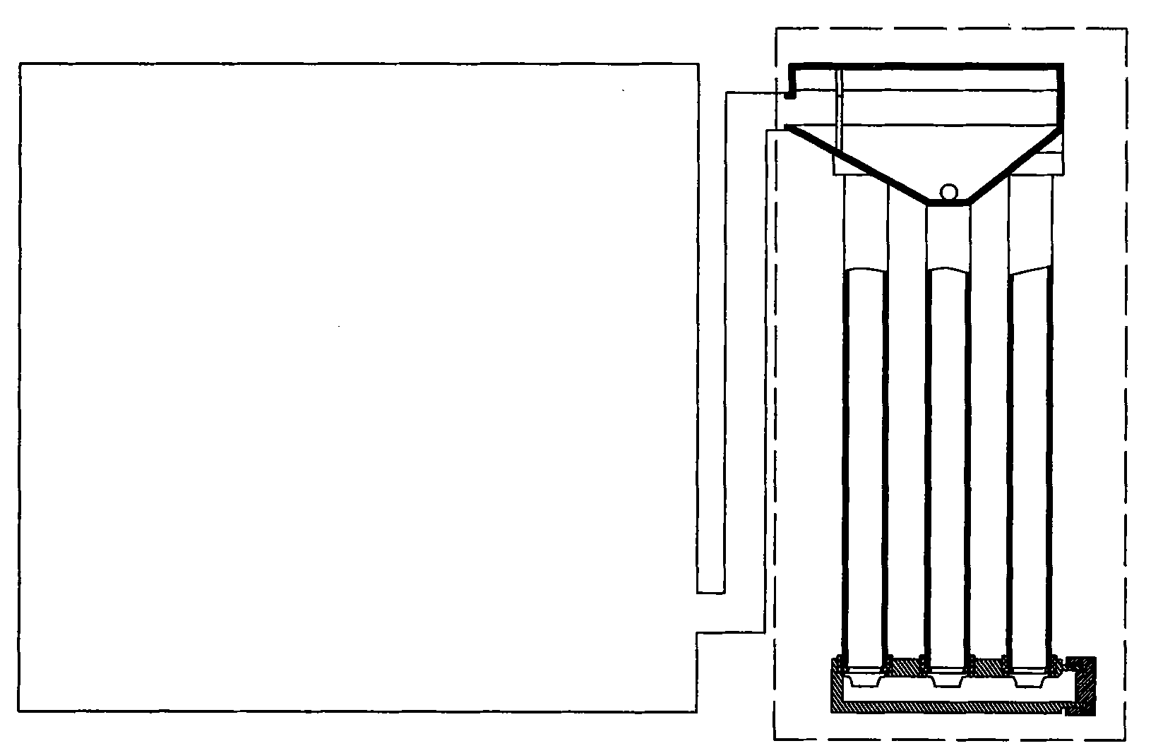
[0046] Such as Figure 9 , Figure 10 As shown, this household electric steamer comprises shell 19, steam chamber 18, steam generator 17, and described steam chamber 18, described steam generator 17 are arranged in described shell 19, are in working state (the steam chamber 18 when the door is closed), the steam chamber 18 communicates with the steam generating device 17 through the pipeline V12 to form a sealed body.

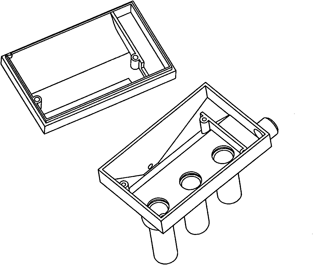
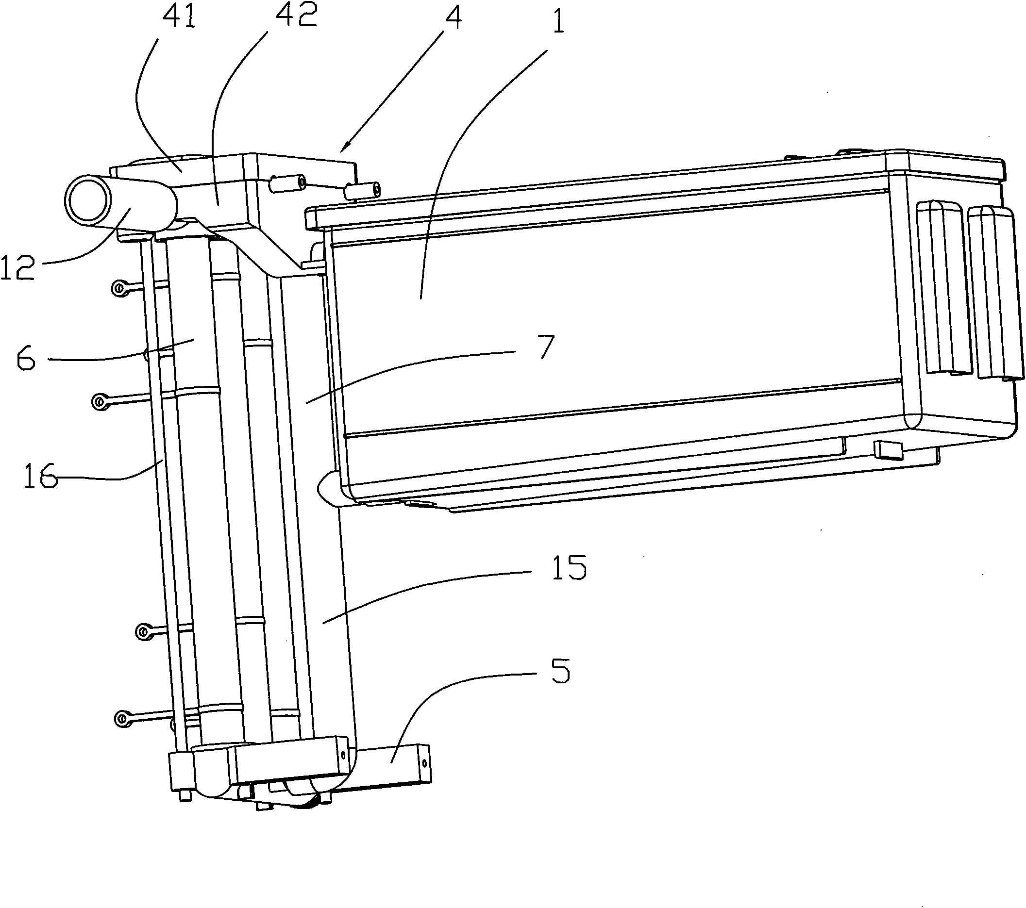
[0047] Such as image 3 As shown, the steam generating device includes a water tank 1 , a steam-water separator 4 including a sealing cover 41 and a base 42 , a water diversion valve 5 , and three heating pipes 6 . Such as Figure 4 As shown, the sealing cover 41 forms a cavity 412 on the top of the base 42 . Such as Figure 7a As shown, the sealing cover includes a baffle I410 and a guide arc 411 . Such as Figure 7b As shown, the base 42 includes a return pipe 421 , a connecting seat pipe 422 , three connecting seats 424 , a baffle II 425 , and a steam...

specific Embodiment 2

[0052] Such as Figure 5 , Figure 7c As mentioned above, compared with the solution in Embodiment 1, the main difference of this embodiment is that the connecting seat tube 422 is arranged on the bottom slope 423, and the connecting seat tube 422 communicates with the pipeline IV 15 through the pipeline III14 (Note that said pipeline III14 and said pipeline IV15 can also be set as one pipeline). The closer the position where the pipe IV 15 communicates with the pipe III 14 is closer to the water outlet 9, the better.

[0053] The difference between the working principle and process of this embodiment and the second embodiment is: the heating pipe 6 heats the water, on the one hand, steam is generated, and the steam enters the right chamber 4122 through the connecting seat 424, and then passes through the incision Enter the left chamber 4121, and then enter the steam chamber 18 through the steam outlet port 426 through the pipeline V12; on the other hand, hot water is genera...

specific Embodiment 3

[0055] Such as Figure 6 , Figure 7d As mentioned above, the main difference between this embodiment and the solution in the first and second embodiments is that the base does not include the connecting seat tube 422, and the pipeline V 12 is tapped with pipelines II 13 (note that the pipeline II 13 and the pipeline V 12 can also be set as a pipeline), and the pipeline II 13 is in communication with the pipeline IV 15 (note that the pipeline II 13 and the pipeline IV 15 can also be set as a pipeline). The pipeline II 13 can be arranged at any position on the pipeline V 12, the closer to the steam chamber 18 the better.

[0056] The difference between the working principle and process of this embodiment and the first and second embodiments is that: the heating pipe 6 heats the water to generate steam on the one hand, and the steam enters the right chamber 4122 through the connecting seat 424, and then passes through the The incision enters the left chamber 4121, and then ent...


PUM


Abstract

The invention discloses a steam generating device, and aims to provide a steam generating device which has the advantages of dry-combustion prevention, energy conservation, water conservation, good steam-water separation effect and simple assembly process. The steam generating device comprises a water tank, a steam-water separator with a sealing cover and a base, a shunt valve and at least one heating tube, wherein a reflow opening on the water tank is communicated with a reflow tube on the base; a bottom plane and a bottom inclined plane are arranged at one end of the bottom surface, close to the reflow tube, of the base; a steam outlet interface is formed on the steam-water separator; a water outlet on the water tank is communicated with the shunt valve through a pipeline IV; and the steam-water separator is communicated with the pipeline IV through a pipeline. The invention also discloses a domestic electric steam box with the steam generating device, which has the advantages of safety, energy conservation and water conservation.

Description

technical field [0001] The invention relates to a steam generating device and a household electric steam box. Background technique [0002] In the prior art, there are various household electric steamers. For example, the applicant applied for a Chinese invention patent on February 12, 2010, with the application number: 201010114441.6 [application name: household steamer], which discloses a household steamer and provides the society with a A household steamer with high boiling water output efficiency and simple assembly process. But the steam generator disclosed in this patent also has the following deficiencies: [0003] 1. When the water outlet of the water storage tank is relatively small (i.e. the flow rate of the water in the water storage tank into the water supply conduit is small), and there is still air in the water supply conduit (equivalent to pipeline IV in the present invention) , it is easy to form a water seal phenomenon at the water outlet, thereby causing...

Claims


Application Information

Patent Timeline
Patent Type & Authority Applications(China)
IPC IPC(8): F22B1/28A47J27/04
CPCF22B1/284F16T1/00F24C15/327
Inventor 张北王天亮黄发喜冯财和
Owner 深圳市北鼎晶辉科技有限公司
Why Eureka
Try Eureka