Side pressure resistant submarine optical fiber cable core

A submarine optical cable, anti-lateral pressure technology, applied in the direction of fiber mechanical structure, etc., can solve the problems of reducing the water tightness of optical fiber units, compressing optical fibers, etc., and achieve the effect of improving tensile and lateral pressure resistance and firm structure

Inactive Publication Date: 2011-01-12
江苏通光海洋光电科技有限公司
View PDF0 Cites 12 Cited by
  • Summary
  • Abstract
  • Description
  • Claims
  • Application Information

AI Technical Summary

Problems solved by technology

Another structure of the existing inner armored optical fiber unit is to use a plurality of steel elements with roughly fan-shaped cross-sections to form a split steel pipe optical fiber unit, which has better resistance to tension and lateral pressure, but this structure is subject to lateral pressure and optical cable. When bending, the steel element will be displaced, there is a risk of compressing the optical fiber and the displacement will create gaps in the steel element, reducing the watertightness of the optical fiber unit

Method used


Image

  • Side pressure resistant submarine optical fiber cable core
  • Side pressure resistant submarine optical fiber cable core
  • Side pressure resistant submarine optical fiber cable core

Examples


Embodiment 1

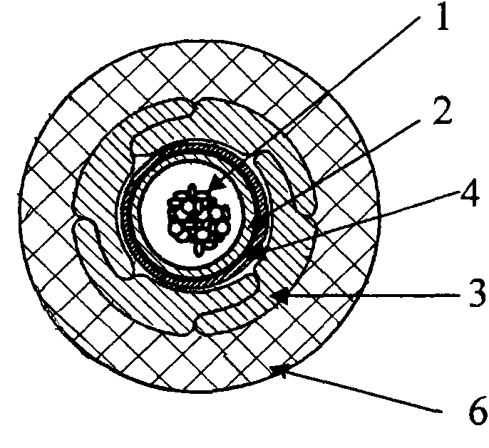
[0010] Embodiment 1, a kind of anti-lateral pressure submarine cable core, see figure 1 , the optical fiber unit protection tube (2) containing the optical fiber (1) and water-blocking fiber paste is longitudinally wrapped with a layer of copper tape (4) for detecting DC resistance, and an anti-corrosion resistance composed of 4 stainless steel special-shaped wires is twisted on the outside. The housing (3) is side-pressed, and a high-density polyethylene insulating sheath layer (6) is extruded on the outermost side. This cable core is mainly used for anti-side pressure non-repeater amplifier submarine optical cable that does not require power feeding but requires detection of insulation resistance.

Embodiment 2

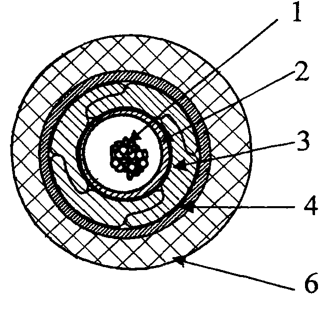
[0011] Embodiment 2, a kind of anti-lateral pressure submarine cable core, see figure 2 , is to directly twist 4 stainless steel special-shaped wires outside the optical fiber unit (1, 2) to form a lateral pressure-resistant shell (3), and cover the feed copper pipe (4) and high-density polyethylene on the outside in turn from the inside to the outside The insulating sheath layer (6), all gaps are filled with water-blocking materials. The cable core is used for side-pressure-resistant submarine cables with relay amplifiers that need to be fed.

Embodiment 3

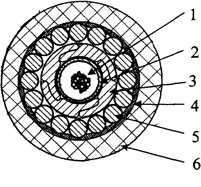
[0012] Embodiment 3, a kind of anti-lateral pressure submarine cable core, see image 3 , which is an anti-lateral pressure shell (3) composed of 4 stainless steel special-shaped wires twisted outside the optical fiber unit (1, 2), and the outer side is covered with inner armored galvanized steel wire (5) and longitudinally wrapped in turn from the inside to the outside. Feed copper pipe (4) and extruded high-density polyethylene insulating sheath (6). The cable core is mainly used to enhance the tensile strength. Relay amplifiers are required for power feeding, which can be directly laid on submarine optical cables in deep sea .


PUM


Abstract

The invention discloses a side pressure resistant submarine optical fiber cable core, which consists of an optical fiber, a protective tube, a side pressure resistant shell, a feed or detection copper tuber or copper strap, an internal armored steel wire, an insulating sheath and a filling wire. The side pressure resistant submarine optical fiber cable core is characterized in that a layer of tubular strong side pressure resistant shell stranded by a special-shaped wire is stranded outside the optical fiber unit. The side pressure resistant submarine optical fiber cable core has the advantages of remarkably improving the tensile stress and side pressure resistance of the cable core, ensuring that the submarine optical fiber is not damaged and facilitating safer and more reliable operation of optical communication along with very firm structure.

Description

technical field [0001] The invention relates to a submarine optical cable for optical fiber communication, in particular to a submarine optical cable core capable of resisting lateral pressure. Background technique [0002] The main structure of the submarine optical cable is the cable core containing the optical fiber unit and the outer armor. The outer armor is the same. The lateral pressure resistance of the submarine optical cable mainly depends on the cable core. The inner armored optical fiber unit of the prior art is to twist one or more layers of round steel wires outside the optical fiber unit, which improves the tensile strength, but the round steel wires are easy to slide, and the gap between the wires or layers is large, so the ability to improve the lateral pressure resistance is limited. . Another structure of the existing inner armored optical fiber unit is to use a plurality of steel elements with roughly fan-shaped cross-sections to form a split steel pipe ...

Claims


Application Information

Patent Timeline
Patent Type & Authority Applications(China)
IPC IPC(8): G02B6/44
Inventor 黄俊华徐军黄豪士陆国钦
Owner 江苏通光海洋光电科技有限公司
Why Eureka
Try Eureka