
Separately-excited synchronous motor magnetic flux orientation method

A synchronous motor and magnetic flux technology, applied in the control of generators, motor generators, electronically commutated motors, etc., can solve the problems of easy failure and high cost, avoid motor stall, less hardware, and avoid out of step and oscillating effects

Active Publication Date: 2011-01-12
通用电气(武汉)自动化有限公司
View PDF3 Cites 8 Cited by
  • Summary
  • Abstract
  • Description
  • Claims
  • Application Information

AI Technical Summary

Problems solved by technology

[0005] The purpose of the present invention is to provide a method for magnetic flux orientation of separately excited synchronous motors, which can overcome the defects of high cost and easy failure of existing synchronous electromagnetic flux orientation methods

Method used


Image

  • Separately-excited synchronous motor magnetic flux orientation method
  • Separately-excited synchronous motor magnetic flux orientation method
  • Separately-excited synchronous motor magnetic flux orientation method

Examples


Embodiment Construction

[0035] Embodiments of the present invention will now be described with reference to the drawings, in which like reference numerals represent like elements.

[0036] In order to explain the flux orientation method of the separately excited synchronous motor in this embodiment more clearly, the structure and working principle of the separately excited synchronous motor are described here.

[0037] A generator consists of a rotor and a stator. There are pairs of magnetic poles and field windings on the rotor. There are three-phase symmetrical AC windings (armature windings) on the stator. After the rotor is dragged by the prime mover (hydraulic turbine, steam turbine, diesel engine, etc.), the rotor rotates around the rotor shaft and inputs mechanical energy to the motor; when the excitation winding of the rotor is supplied with DC excitation current, an excitation magnetic field (main magnetic field) is established in the air gap of the motor , the excitation magnetic field ro...


PUM


Abstract

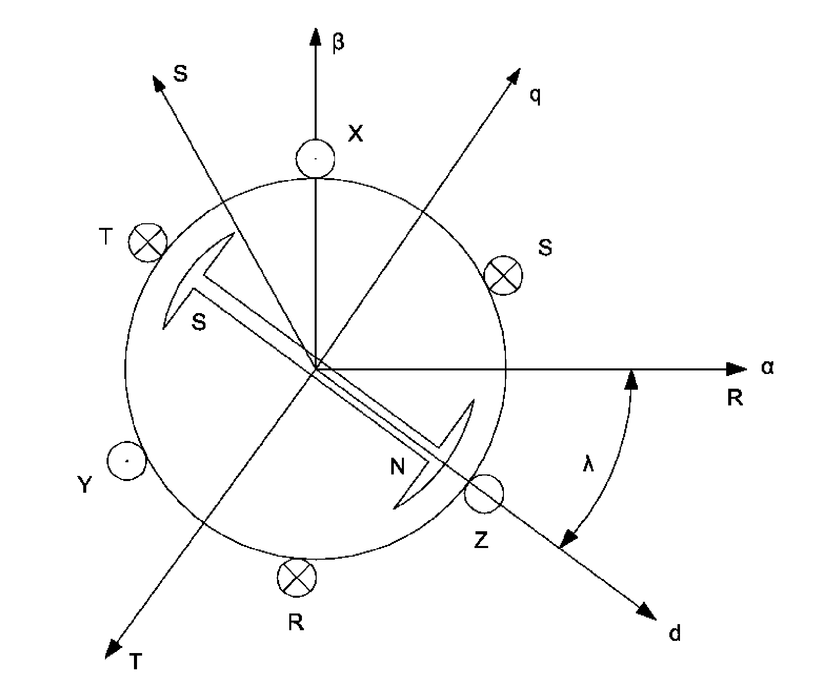
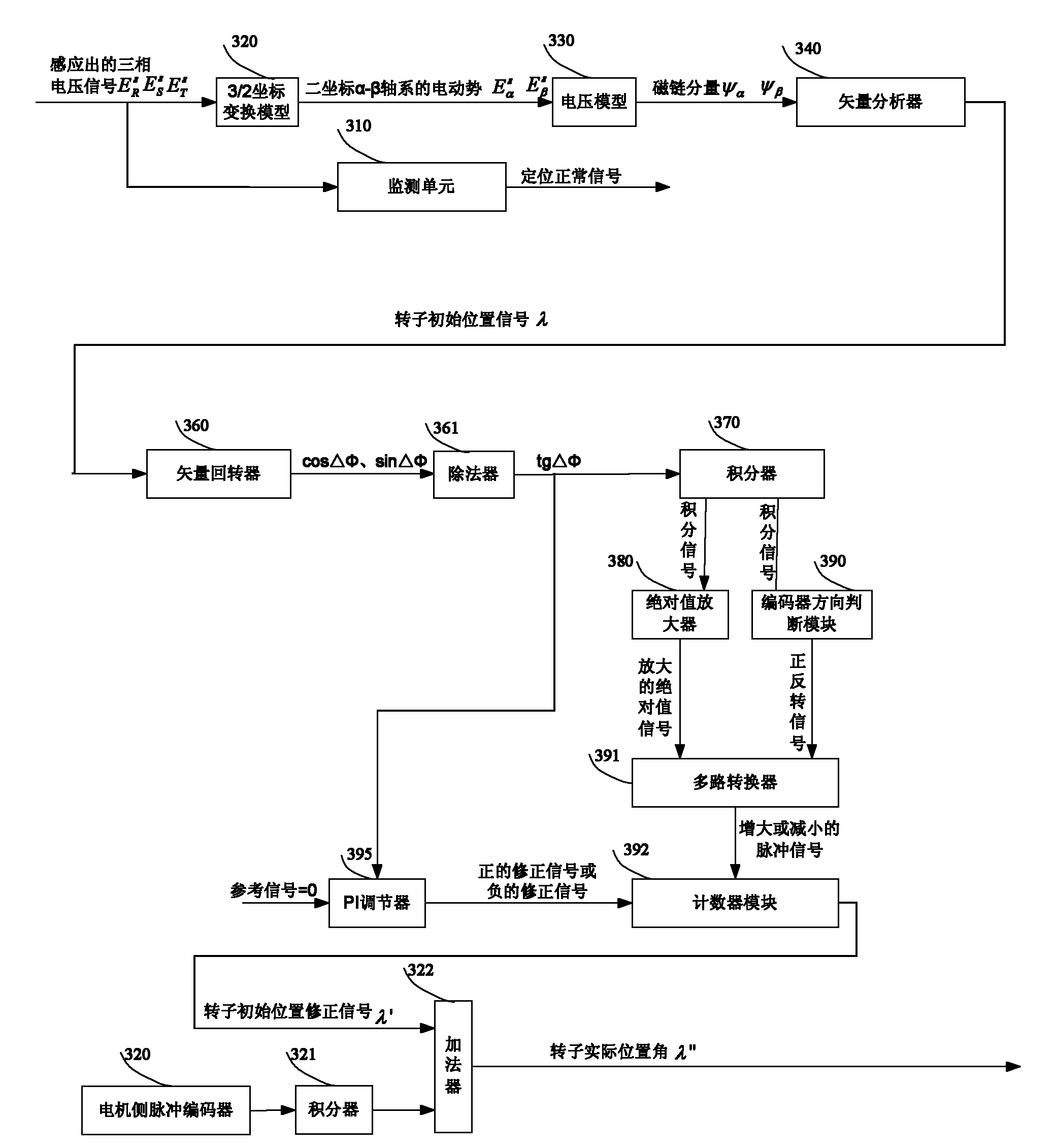
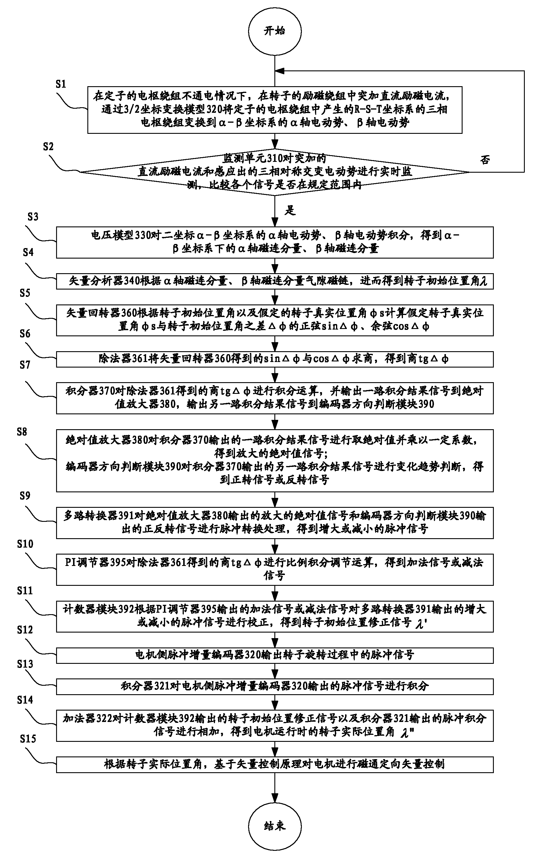
The invention discloses a separately-excited synchronous motor magnetic flux orientation method, which comprises the following steps of: performing 3 / 2 coordinate transformation on three phases of armature windings produced in the armature winding of a stator to obtain an alpha-axis electromotive force and a beta-axis electromotive force to acquire an initial rotor position angle; computing the tangent of a difference between a supposed actual rotor position angle and the initial rotor position angle; integrating the computed tangent, taking absolute values of a path of integrated signals, multiplying the absolute values by a certain coefficient, judging the variation trend of the other path of integrated signals, and performing pulse conversion processing on the two paths of processed integrated signals; performing proportional integral control operation on the computed tangent; correcting the signals subjected to the pulse conversion processing by using the signals subjected to the control operation to obtain initial rotor position correction signals; integrating pulse signals in the rotating process of a rotor; and adding the initial rotor position correction signals and the pulse integrated signals to obtain an actual rotor position angle to perform magnetic flux orientation vector control on the motor. The method has the advantage of realizing the low cost and low failurerate of magnetic flux orientation.

Description

technical field [0001] The invention relates to a speed regulation control technology of a synchronous motor, in particular to a magnetic flux orientation method of a separately excited synchronous motor. Background technique [0002] Synchronous motor is a kind of AC rotating motor. It is named because its speed is equal to the synchronous speed. Synchronous motor is mainly used as a generator, and can also be used as a motor and a condenser. [0003] Modern AC synchronous motor control generally adopts flux-oriented vector control technology. The horizontal axis of the reference rotating coordinate system of this technology is located on the axis of the motor flux and flux linkage. At this time, the angle between the stationary and rotating coordinate systems cannot be obtained directly, and real-time It is obtained by calculating the rotor position of the motor, so the process of flux orientation of the AC synchronous motor is also the process of positioning the rotor pos...

Claims


Application Information

Patent Timeline
Patent Type & Authority Applications(China)
IPC IPC(8): H02P21/14H02P21/18H02P21/26
Inventor 潘端南金林王杲周子伟尹幼华
Owner 通用电气(武汉)自动化有限公司
Learn More