Brake control apparatus

A technology of brake control and equipment, applied in the direction of brakes, etc., can solve problems such as insufficient performance, and achieve the effects of suppressing pressure drop, improving braking feeling, and suppressing changes in capacity

Inactive Publication Date: 2011-01-12
TOYOTA JIDOSHA KK
View PDF4 Cites 20 Cited by
  • Summary
  • Abstract
  • Description
  • Claims
  • Application Information

AI Technical Summary

Problems solved by technology

The same problem can occur if the pump fails and does not perform adequately

Method used


Image

  • Brake control apparatus
  • Brake control apparatus
  • Brake control apparatus

Examples


Embodiment Construction

[0035] Hereinafter, exemplary embodiments of the present invention will be described with reference to the accompanying drawings. In the description for the drawings, the same or corresponding parts are denoted by the same reference numerals. The following provides only one description of parts with the same reference numerals.

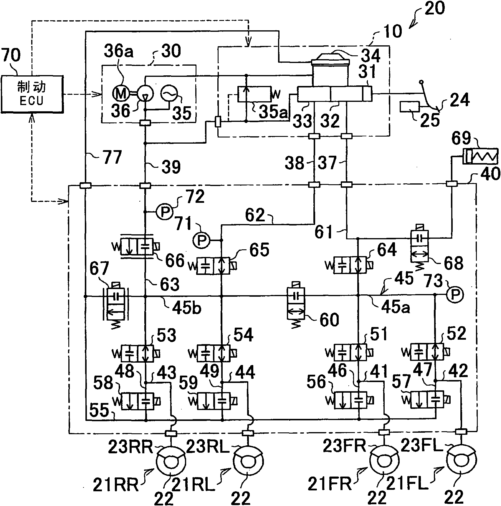
[0036] Next, a first embodiment of the present invention will be described. figure 1 is a system view showing the brake control apparatus 20 according to the first embodiment of the present invention. figure 1 The illustrated brake control device 20 forms an electronically controlled braking system for a vehicle and controls the braking force applied to the four wheels of the vehicle. The brake control apparatus 20 according to the first embodiment of the present invention is mounted, for example, on a hybrid vehicle provided with an electric motor and an internal combustion engine as driving power sources. In a hybrid vehicle, braking may be appli...


PUM


Abstract

In a brake control apparatus (20) that controls braking forces which are applied to wheels based on the pressure of a brake fluid, when a hydraulic pressure actuator (40) controls the hydraulic pressure that is transferred to wheel cylinders (23) using the hydraulic pressure of the brake fluid in a power hydraulic pressure source (30), a brake ECU (70) closes a simulator cut valve (68) if the pressure of the brake fluid in the power hydraulic pressure source (30) falls below a predetermined value (Pssc) or if it is determined that the number of times the brake operation member (24) is operated within a predetermined value. In addition, the ECU (70) may change the timing for closing the simulator cut valve (68) based on the road surface condition estimated at the time of antilock control start. Thus, a driver is less likely to feel unusual brake feel when a braking control mode is changed.

Description

technical field [0001] The present invention generally relates to a brake control device and a brake control method that control braking force applied to wheels of a vehicle, and more particularly, to a technique for improving brake feeling using the brake control device. Background technique [0002] There is a hydraulic control device that generates hydraulic pressure corresponding to an operation amount of a brake pedal in a hydraulic circuit and supplies the hydraulic pressure generated in the hydraulic circuit to wheel cylinders, thereby applying braking force to wheels of a vehicle. In addition, there is a hydraulic control device provided with an actuator including a pair of solenoid control valves for increasing or decreasing the wheel cylinder supplied to each wheel, and an electronic control unit controlling the actuator. internal pressure. With this hydraulic control device, the amount by which the brake pedal is operated by the driver is detected by, for example...

Claims


Application Information

Patent Timeline
Patent Type & Authority Applications(China)
IPC IPC(8): B60T8/40
CPCB60T8/4081
Inventor 酒井朗门崎司朗福田光雄中村荣治
Owner TOYOTA JIDOSHA KK
Why Eureka
Try Eureka