Material clamping block for multi-clamp type stretch forming machine

A stretch forming and clamp-type technology, which is applied in the field of clamping blocks for multi-clamp stretch forming machines, can solve the problems of expensive equipment, cracking or wrinkling, and reduced material utilization, so as to improve the quality of materials. Utilization rate, effect of stretch forming

Inactive Publication Date: 2011-01-19
JILIN UNIV
View PDF5 Cites 2 Cited by
  • Summary
  • Abstract
  • Description
  • Claims
  • Application Information

AI Technical Summary

Problems solved by technology

[0002] When the traditional stretch forming machine draws the workpiece, the plate at the jaws basically moves along the horizontal direction; when forming a workpiece with a large transverse curvature, the distribution of tensile stress and strain in the transverse direction of the plate is obviously uneven, which is easy to cause non-fitting, Forming defects such as tearing or wrinkling
In order to prevent these defects, the control accuracy of the equipment is very high, the design of the control system is complicated, and the equipment is expensive; moreover, the blanks for drawing often require a large process margin, which leads to a reduction in the utilization rate of materials

Method used


Image

  • Material clamping block for multi-clamp type stretch forming machine
  • Material clamping block for multi-clamp type stretch forming machine
  • Material clamping block for multi-clamp type stretch forming machine

Examples


Embodiment Construction

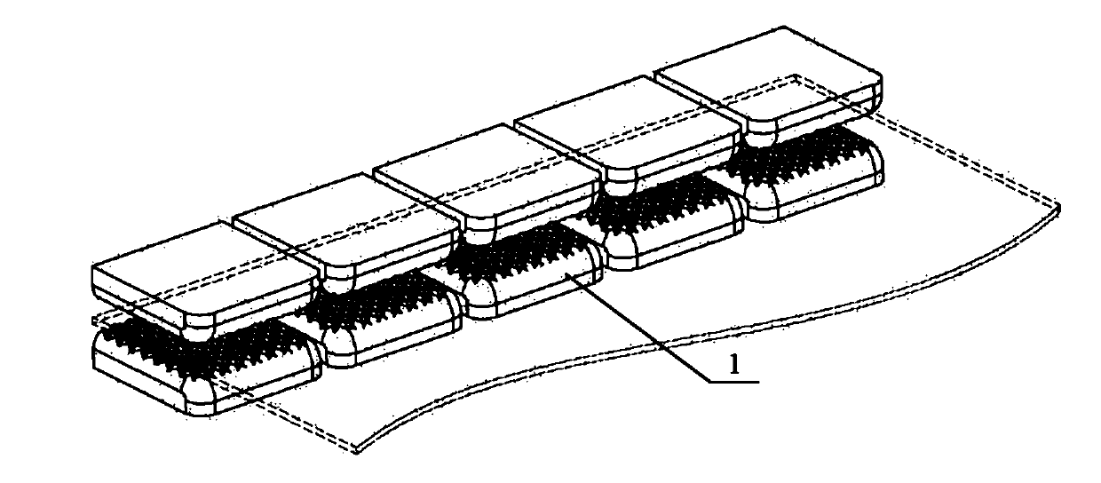
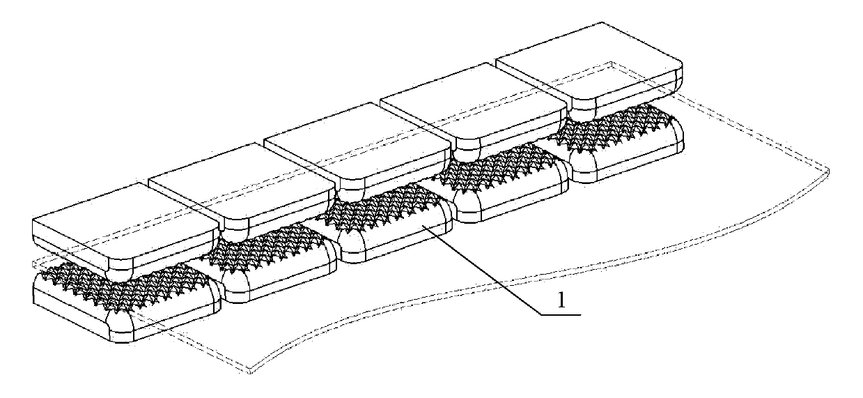
[0022] The specific content and working process of the present invention will be further described below in conjunction with the embodiments shown in the accompanying drawings.

[0023] figure 1 It is a schematic diagram of using multiple pairs of clamping blocks 1 . A row of five pairs of gripping clamping blocks 1 are arranged on the left and right sides of the stretch forming machine respectively; there is a certain gap between the adjacent clamping blocks, and there are Large rounded corners, and there are certain rounded corners at the ridges at the left and right ends of the sandwiching surface adjacent to other sandwiching blocks. In this way, the flow and extension of the sheet material are allowed to occur in places with gaps and rounded corners. The clamping surface adopts a clamping type with many protrusions, which can clamp the sheet material tightly. During the stretch forming process of the sheet metal, the sheet material basically cannot flow in the clamping ...


PUM


Abstract

The invention discloses a material clamping block for a multi-clamp type stretch forming machine, relating to a plastic processing device for curve surface forming of sheet parts and belonging to the field of mechanical engineering. The material clamping block comprises two rows of multiple pairs, and the two rows are respectively arranged on the left side and the right side of the stretch forming machine. A gap is reserved between two adjacent material clamping blocks, a chine line and two angles on the front end of the material clamping face of each material clamping block are large rounded corners, and chine lines on the left end and the right end of the material clamping surface adjacent to other material clamping blocks are also provided with round corners. The design allows each material clamping block and a material clamping mechanism to passively produce unequal rotation, swinging or stretching to form arc or waveform linear parallelism, and the flexible control of multiple clamps of the stretch forming machine is realized; and the invention is beneficial to a workpiece to snuggle to a mold during stretching, the material utilization rate of the workpiece is obviously increased, and the stretching forming of a complex workpiece is realized.

Description

technical field [0001] The clamping block for a multi-clamp stretch forming machine of the present invention relates to plastic processing equipment for forming curved surfaces of plate parts, and belongs to the field of mechanical engineering. Background technique [0002] When the traditional stretch forming machine draws the workpiece, the plate at the jaw basically moves along the horizontal direction; when forming a workpiece with a large transverse curvature, the distribution of tensile stress and tensile strain in the transverse direction of the plate is obviously uneven, which is easy to cause non-fitting, Forming defects such as tearing or wrinkling. In order to prevent these defects, the control accuracy of the equipment is very high, the design of the control system is complicated, and the equipment is expensive; moreover, the blanks for drawing often require a large process margin, which leads to a decrease in the utilization rate of materials. Contents of the ...

Claims


Application Information

Patent Timeline
Patent Type & Authority Applications(China)
IPC IPC(8): B21D22/22
Inventor 李明哲韩奇钢冯朋晓蔡中义阎雪萍
Owner JILIN UNIV
Why Eureka
Try Eureka