Continuous loose fiber dyeing machine

A dyeing machine and dyeing cylinder technology, applied in the field of dyeing machines, can solve problems such as being unfavorable for large roll work, waste dyes, and large roll workload, etc., and achieve the effects of improving dye penetration, saving consumption and reducing workload

Active Publication Date: 2011-01-19
新昌县艺力机械有限公司 +1
View PDF4 Cites 9 Cited by
  • Summary
  • Abstract
  • Description
  • Claims
  • Application Information

AI Technical Summary

Problems solved by technology

Loose loose fiber absorbs a lot of dye when dyeing, and when it is dried, a lot of dye is squeezed out, so a lot of dye is wasted
In addition, the loos

Method used


Image

  • Continuous loose fiber dyeing machine
  • Continuous loose fiber dyeing machine

Examples


Embodiment

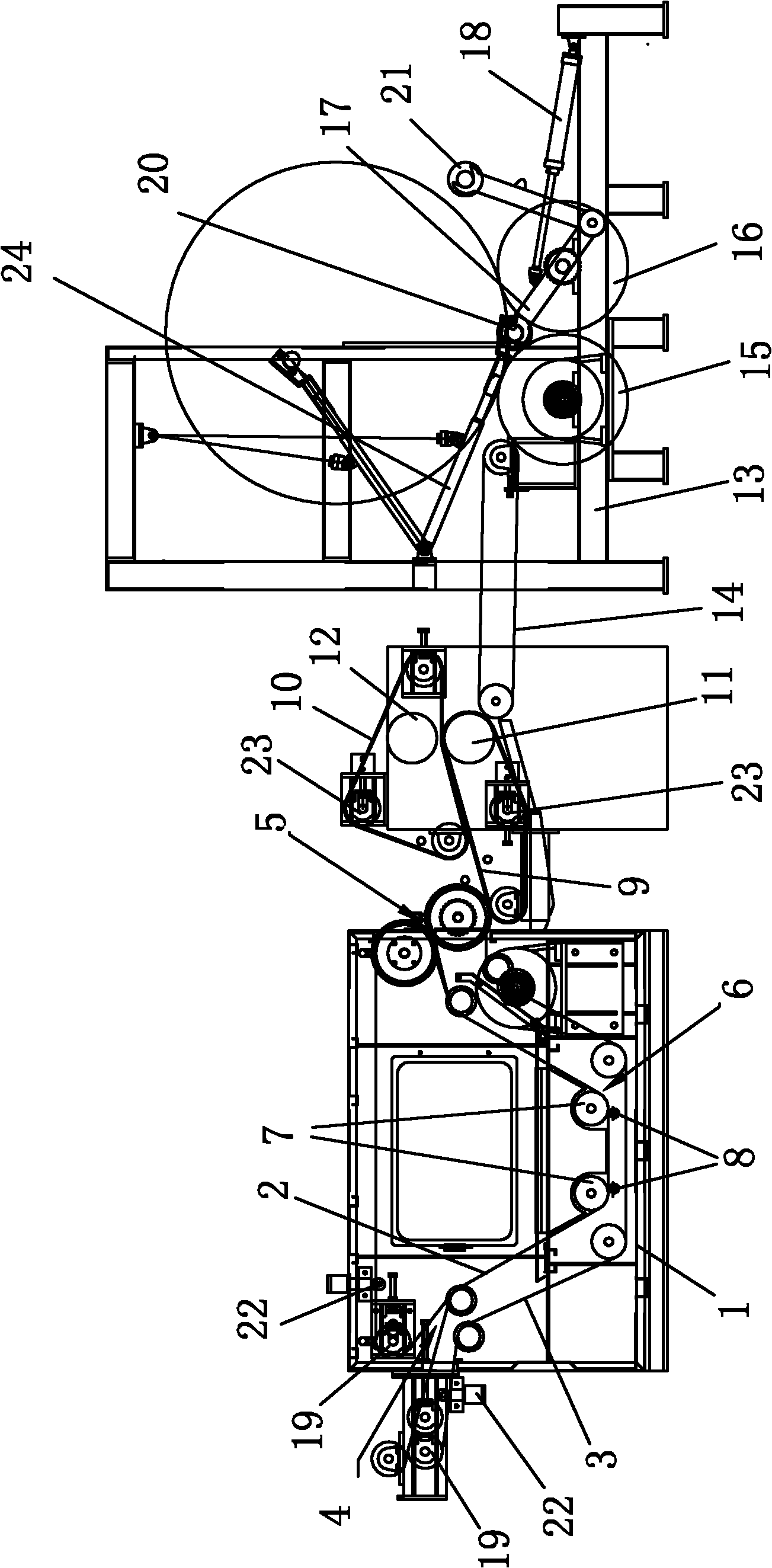
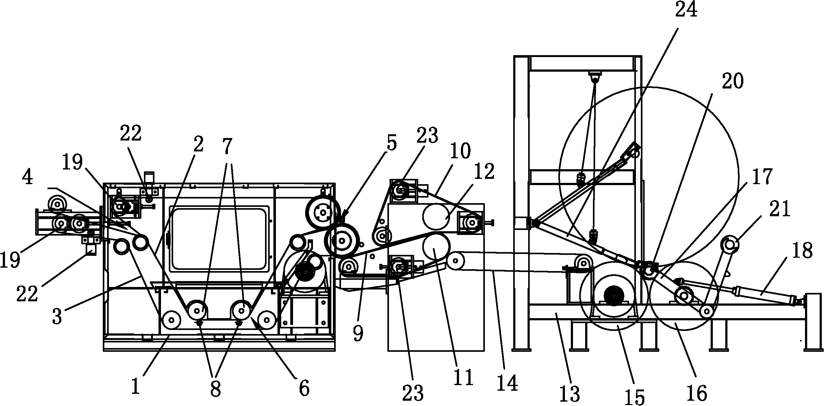
[0016] Example: Continuous bulk fiber dyeing machine, such as figure 1 As shown, it includes a dyeing vat 1, and the mechanism for conveying loose fibers matched with the dyeing vat 1 is a double-mesh belt dyeing conveying mechanism, which includes two closed endless mesh belts A2 and endless mesh belt B3, The transmission components that are respectively matched with the transmission of each dyeing mesh belt, the two ring-shaped dyeing mesh belts located in the dyeing vat 1 are interstitially stacked and matched, and the two ring-shaped dyeing mesh belts that are respectively matched with the inlet and outlet ends of the dyeing vat 1 A duckbill-shaped input port 4 and a duckbill-shaped output port 5 are respectively formed, and two ring-shaped dyeing mesh belts located outside the dyeing vat 1 cooperate with respective transmission components to form a ring-shaped transmission. The loose fiber is clamped and transported to the dyeing vat by the double mesh belt dyeing conveyi...


PUM


Abstract

The invention relates to a continuous loose fiber dyeing machine. The continuous loose fiber dyeing machine comprises a dye vat; a mechanism which is fitted with the dye vat and used for conveying loose fibers is a double mesh belt dyeing conveying mechanism, and the double mesh belt dyeing conveying mechanism comprises two closed mesh belts (namely, a ring mesh belt A and a ring mesh belt B) and transmission components which are respectively in transmission fit with each ring mesh belt; two ring dyeing mesh belts in the dye vat are in clearance stacking fit with each other, the two ring dyeing mesh belts respectively fitted with the inlet end and the outlet end of the dye vat respectively form a duckbilled input port and a duckbilled output port, and the two ring dyeing mesh belts arranged outside the dye vat are respectively fitted with the respective transmission components so as to form a circular transmission. The invention has the prominent and substantive effects as follows: because the loose fibers are clamped and then sent to the dye vat for dyeing and the loose fiber is thin, the loose fiber is easy to be dyed completely; and with the help of shower pipes, the dye permeability of the loose fibers is improved, and little dyes are taken away, therefore, the dye consumption is saved.

Description

Technical field [0001] The invention relates to a dyeing machine, in particular to a continuous loose fiber dyeing machine for dyeing loose fibers. Background technique [0002] Existing equipment for loose fiber dyeing usually only includes a dyeing vat, and loose loose fibers are put into the dyeing vat, and after dyeing, the loose fibers are rolled and dried. Loose loose fiber absorbs a lot of dye when dyeing, and when it is dried, it squeezes out a lot of dye, so a lot of dye is wasted. In addition, the loose fibers after dyeing and padding are adhered to one piece, which is not conducive to the work of large rolls, and the workload of large rolls is heavy. Contents of the invention [0003] The purpose of the present invention is to provide a continuous loose fiber dyeing machine. The loose fiber is evenly laid between the two dyeing mesh belts of the double mesh belt dyeing conveying mechanism, and the loose fiber is clamped and transported to the dyeing vat for dye...

Claims


Application Information

Patent Timeline
IPC IPC(8): D06B3/02D06B23/14D06B23/04
Inventor 陈胜挺陈明军
Owner 新昌县艺力机械有限公司
Why Eureka
Try Eureka