Polarization color separation and combination device with low polarization aberration

A low-polarization, polarization separation technology, applied in instruments, optical components, optics, etc., can solve the problems of stray light, prism and film surface thermal aberration, large polarization separation, etc., to achieve the effect of good projection effect

Active Publication Date: 2011-01-19
HANGZHOU KOTI OPTICAL TECH
View PDF3 Cites 2 Cited by
  • Summary
  • Abstract
  • Description
  • Claims
  • Application Information

AI Technical Summary

Problems solved by technology

[0003] Due to the large polarization aberration, the polarization separation and color combination devices of existing reflective projectors are not enough for large-scale display systems with ultra-high brightness and ultra-high definition. The main technical problems are: short-wave pass film and long-wave pass film The S and P polarization separation of the transmission spectroscopic curve is large, which not only leads to the loss of light energy, but also the lost part of the light becomes stray light after multiple reflections and refractions in the device, resulting in a decrease in image clarity and contrast; short-wave pass film The S and P polarization phase difference synthesized with the long-wave pass film is too large, so that part of the light changes from linearly polarized light to oblate elliptical polarized light. Since the incident light of the polarization separation and color combination device is S linearly polarized light, the modulated signal light is P Linearly polarized light and S-polarized component in oblate elliptical polarized light will also lead to loss of light energy and introduction of stray light; too high temperature between prism and film during ultra-high brightness operation will lead to failure of prism and film bonding and thermal change of film surface Aberrations, even causing prisms to break

Method used


Image

  • Polarization color separation and combination device with low polarization aberration
  • Polarization color separation and combination device with low polarization aberration
  • Polarization color separation and combination device with low polarization aberration

Examples


Embodiment Construction

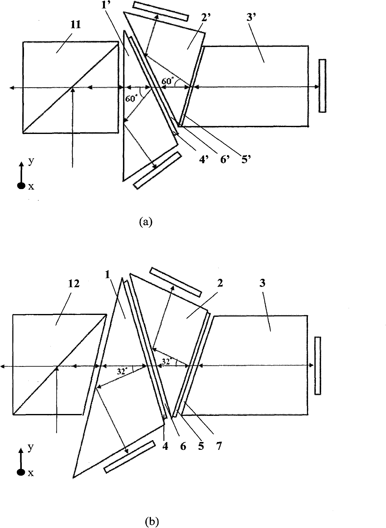
[0042] like figure 1 As shown, the polarization separation and color separation device of the present invention includes a red-transparent blue-green color separation prism 1 , a blue-transmission green separation color separation prism 2 and a green-transmission color separation color combination prism 3 .

[0043] On the second prism surface of the anti-red transparent blue-green color separation prism 1, a short-wave pass film system 4 is coated, so that the S-polarized white light incident on the anti-red transparent blue-green color separation prism 1 is divided into two paths:

[0044] One of them is: the reflected S-polarized red light is totally reflected by the first prism surface of the anti-red transparent blue-green color separation prism 1, and then incident on the red light image modulation by the third prism surface of the anti-red transparent blue-green color separation prism 1 8; the S-polarized red light is modulated by the red-light image modulator 8 to form...


PUM

PropertyMeasurementUnit
Angleaaaaaaaaaa
Angleaaaaaaaaaa

Abstract

The invention discloses a polarization color separation and combination device with low polarization aberration. A short-wave pass film is coated on a second prism face of a red-reflecting and blue and green-transmitting color separation and combination prism; a long-wave pass film is coated on the second prism face of a blue-reflecting and green-transmitting color separation and combination prism; the short-wave pass film on the second prism face of the red-reflecting and blue and green-transmitting color separation and combination prism is parallel to the first prism face of the blue-reflecting and green-transmitting color separation and combination prism and an air gap is reserved between the two; an included angle between the first prism face of the red-reflecting and blue and green-transmitting color separation and combination prism and the second prism face of the red-reflecting and blue and green-transmitting color separation and combination prism is 32 to 40 degrees; the included angle between the first prism face of the blue-reflecting and green-transmitting color separation and combination prism and the second prism face of the blue-reflecting and green-transmitting color separation and combination prism is 32 to 40 degrees; and the long-wave pass filter on the second prism face of the blue-reflecting and green-transmitting color separation and combination prism is parallel to an incident face of the green-transmitting color separation and combination prism and an air gap is reserved between the two. The device has the advantages of improving the utilization ratio of light energy and image definition and contrast, along with poor low-polarization aberration.

Description

technical field [0001] The invention relates to a polarization separation and color combination device with low polarization aberration for a reflective projector. Background technique [0002] The development trend of digital projection display is to develop towards two "extremes". On the one hand, it is developing towards the so-called "pico-projection" micro-display system; Development of large display systems. In various occasions such as movie theaters, large-scale intelligent command posts, and large-scale gatherings, people are calling for a large-screen projection display technology with ultra-high brightness and ultra-high definition. Therefore, how to improve the utilization rate of light energy and increase the display brightness to more than 10,000 lumens is an urgent problem to be solved; how to improve the ultra-high definition display (1920×1280) from 2K pixels to 4K pixels Another problem solved. [0003] Due to the large polarization aberration, the polar...

Claims


Application Information

Patent Timeline
IPC IPC(8): G02B27/28G02B27/18G03B21/20
Inventor 艾曼灵张梅骄金波陶占辉顾培夫唐晋发
Owner HANGZHOU KOTI OPTICAL TECH
Why Eureka
Try Eureka