Flyback synchronous rectification control circuit

A synchronous rectification and control circuit technology, which is applied in the direction of electrical components, AC power input conversion to DC power output, output power conversion devices, etc., can solve the problems of low power efficiency and reliability, and large loss of synchronous rectification circuit components. Achieve the effects of improving efficiency, avoiding reverse current flow, reducing loss and voltage stress

Inactive Publication Date: 2011-01-19
SHENZHEN VAPEL POWER SUPPLY TECH
View PDF5 Cites 24 Cited by
  • Summary
  • Abstract
  • Description
  • Claims
  • Application Information

AI Technical Summary

Problems solved by technology

[0006] In order to solve the defects of large loss of synchronous rectification circuit components and low power supply efficiency and reliability in the prior art, the present invention provides a primary switching tube (Q1), a synchronous rectifying tube (Q2), the primary side of the main transformer (T1), and the main transformer The secondary side and synchronous rectification module of (T1) is characterized in that: it also includes drive circuit (1), delay circuit (2), signal in-phase transmission circuit (3), sharp pulse forming circuit (4) and synchronous rectification forced A control circuit composed of a shu

Method used


Image

  • Flyback synchronous rectification control circuit
  • Flyback synchronous rectification control circuit
  • Flyback synchronous rectification control circuit

Examples


Embodiment 1

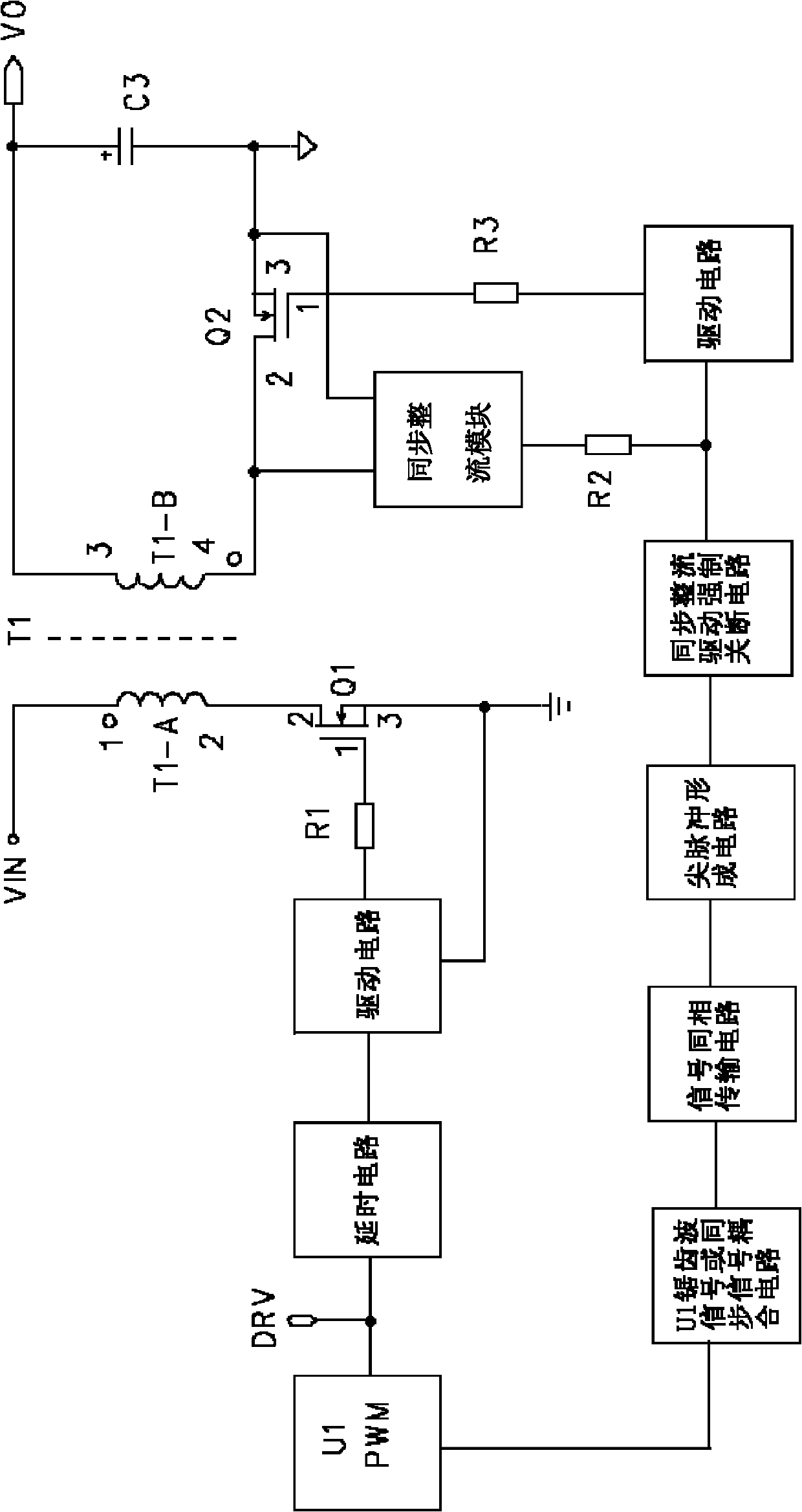
[0023] The flyback synchronous rectification circuit of this embodiment is as figure 2 As shown, it includes a primary switch tube Q1, a synchronous rectifier tube Q2, the primary side of the main transformer T1, the secondary side of the main transformer T1 and a synchronous rectification module, the synchronous rectification module is a synchronous rectification circuit or a control IC; A control circuit composed of a drive circuit 1, a delay circuit 2, a signal in-phase transmission circuit 3, a spike forming circuit 4 and a synchronous rectification forced shutdown circuit 5, the delay circuit 2 and the drive circuit 1 are connected in series, and the delay circuit 1 The other end of the drive circuit 1 receives the PWM signal U1 and the drive signal DRV, the other end of the drive circuit 1 is connected to the gate of the primary switching tube Q1, the signal in-phase transmission circuit 3, the spike forming circuit 4, the synchronous rectification forced shutdown circui...

Embodiment 2

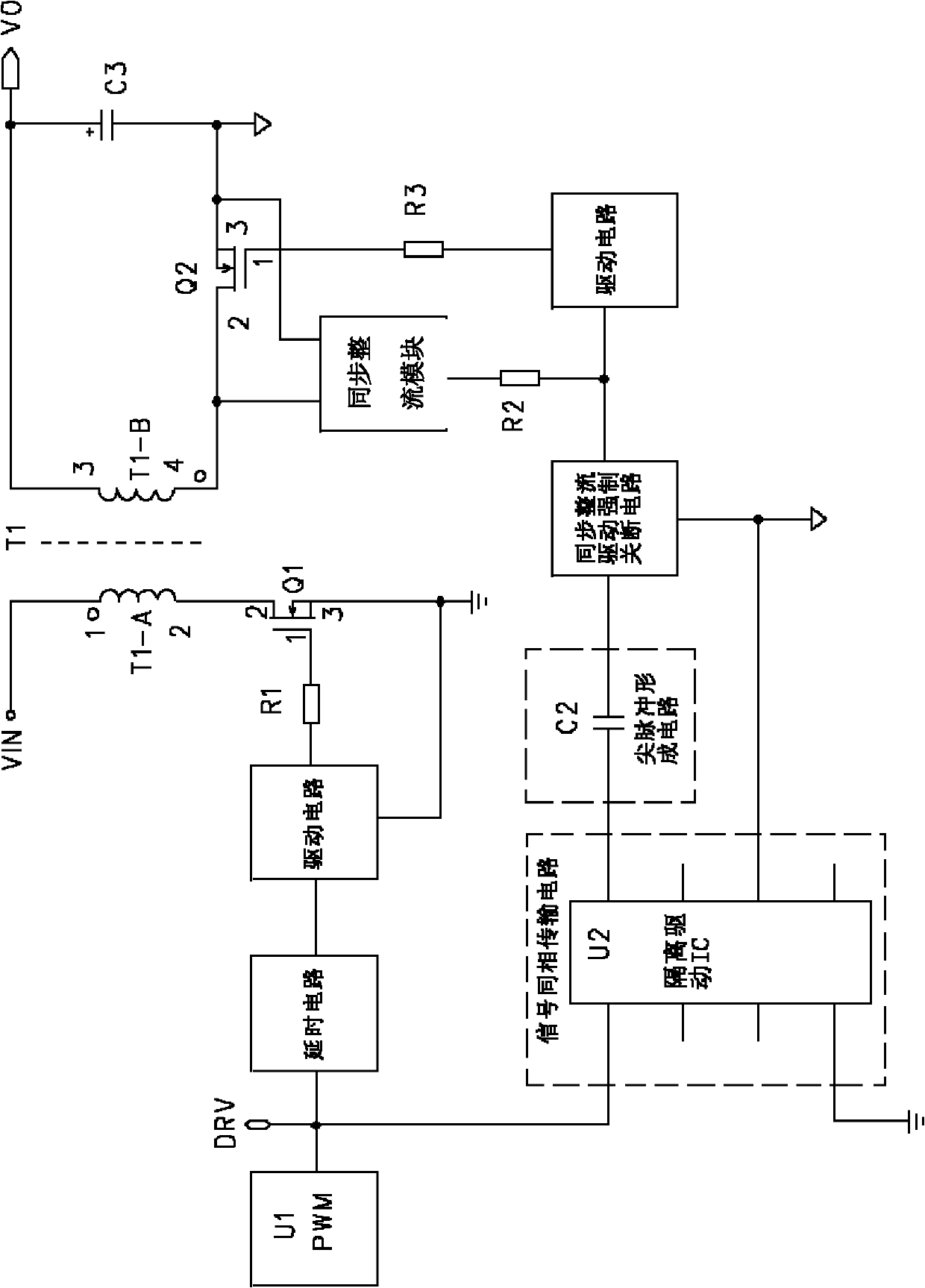
[0026] The flyback synchronous rectification circuit of this embodiment is as image 3 As shown, the difference between it and the foregoing embodiment 1 is that it also includes a drive circuit 6, whose input terminal is connected to the synchronous rectification forced shutdown circuit 5, and is connected to the synchronous rectification module through a resistor R2, and the output terminal is connected to the synchronous rectification module through a resistor R3 It is connected with the gate of the synchronous rectifier Q2.

[0027] In this embodiment, by adding the drive circuit 6 and the protection resistors R2 and R3, the whole circuit can work more stably and reliably.

Embodiment 3

[0029] like Figure 4 As shown, the circuit of this embodiment includes a primary switch tube Q1, a synchronous rectifier tube Q2, a primary side of the main transformer T1, a secondary side of the main transformer T1, and a synchronous rectification module, and the synchronous rectification module is a synchronous rectification circuit or a control IC ; Also comprising a control circuit composed of a drive circuit 1, a time delay circuit 2, a signal in-phase transmission circuit 3, a spike forming circuit 4 and a synchronous rectification forced shutdown circuit 5, the time delay circuit 2 and the drive circuit 1 are connected in series, The other end of the delay circuit 1 receives the PWM signal U1 and the drive signal DRV, the other end of the drive circuit 1 is connected to the gate of the primary switching tube Q1, the signal in-phase transmission circuit 3, the spike forming circuit 4, the synchronous rectification The forced shut-off circuit 5 is sequentially connected...


PUM


Abstract

The invention relates to a flyback synchronous rectification control circuit, comprising a primary switching tube (Q1), a synchronous rectifier tube (Q2), a primary side of a main transformer (T1), a subsidiary side of the main transformer (T2), a synchronous rectifier module, a control circuit composed of a drive circuit (1), a delay circuit (2), a signal same-phase transmission circuit (3), a sharp pulse forming circuit (4) and a synchronous rectification forcibly turned-off circuit (5). When a power source operates in a continuous mode, the synchronous rectifier tube (Q2) can be forcibly turned off in advance through the control circuit, thus reverse current can not pass through the synchronous rectifier tube (Q2), thereby reducing the loss and the voltage stress of the synchronous rectifier tube (Q2), and improving the efficiency of the power source; and when the power source operates in a discontinuous mode or in a critical continuous mode, the control circuit is inoperative, and can not influence the normal operation of the circuit.

Description

technical field [0001] The invention relates to a switching power supply, in particular to a flyback synchronous rectification control circuit for the switching power supply to work in a continuous mode. Background technique [0002] With the development of technology, the conversion efficiency of the power supply is required to be higher and higher, and it has become a trend to replace the traditional diode rectification with synchronous rectification. Traditional synchronous rectification circuits such as figure 1 , its working principle is: use the forward voltage drop and reverse voltage drop generated by the current flowing through the rectifier tube (MOSFET) to control, when it is detected that the forward voltage drop across the rectifier tube reaches a certain set threshold At this point, the synchronous rectification circuit or control IC drives the rectifier to turn on; once the voltage drop at both ends drops to zero or there is a reverse voltage drop, the contro...

Claims


Application Information

Patent Timeline
IPC IPC(8): H02M7/217
Inventor 钟启豪李战伟刘晴宗
Owner SHENZHEN VAPEL POWER SUPPLY TECH
Why Eureka
Try Eureka