
Carbon fiber heating source and heating system using the same

A carbon fiber heating and heating system technology, used in electric heating systems, heating systems, heating methods, etc., can solve the problems of carbon fiber impact resistance and weak tension, carbon fiber cannot be bent or folded, and resistance is easily broken or damaged. High tensile strength, oxidation prevention, high safety effect

Inactive Publication Date: 2011-01-19
ECO CARBON ENERGY CO LTD
View PDF7 Cites 9 Cited by
  • Summary
  • Abstract
  • Description
  • Claims
  • Application Information

AI Technical Summary

Problems solved by technology

However, this method has problems because the vacuum tube prevents efficient transfer from the carbon fiber to the outside
[0011] In addition, the above-mentioned carbon fiber heat generating source is obtained through a complicated process that requires a long time and high cost
Also, carbon fiber is easily broken or damaged due to its weak resistance against impact and tension
In addition, carbon fiber cannot be bent or folded, so it must be used in its original form

Method used


Image

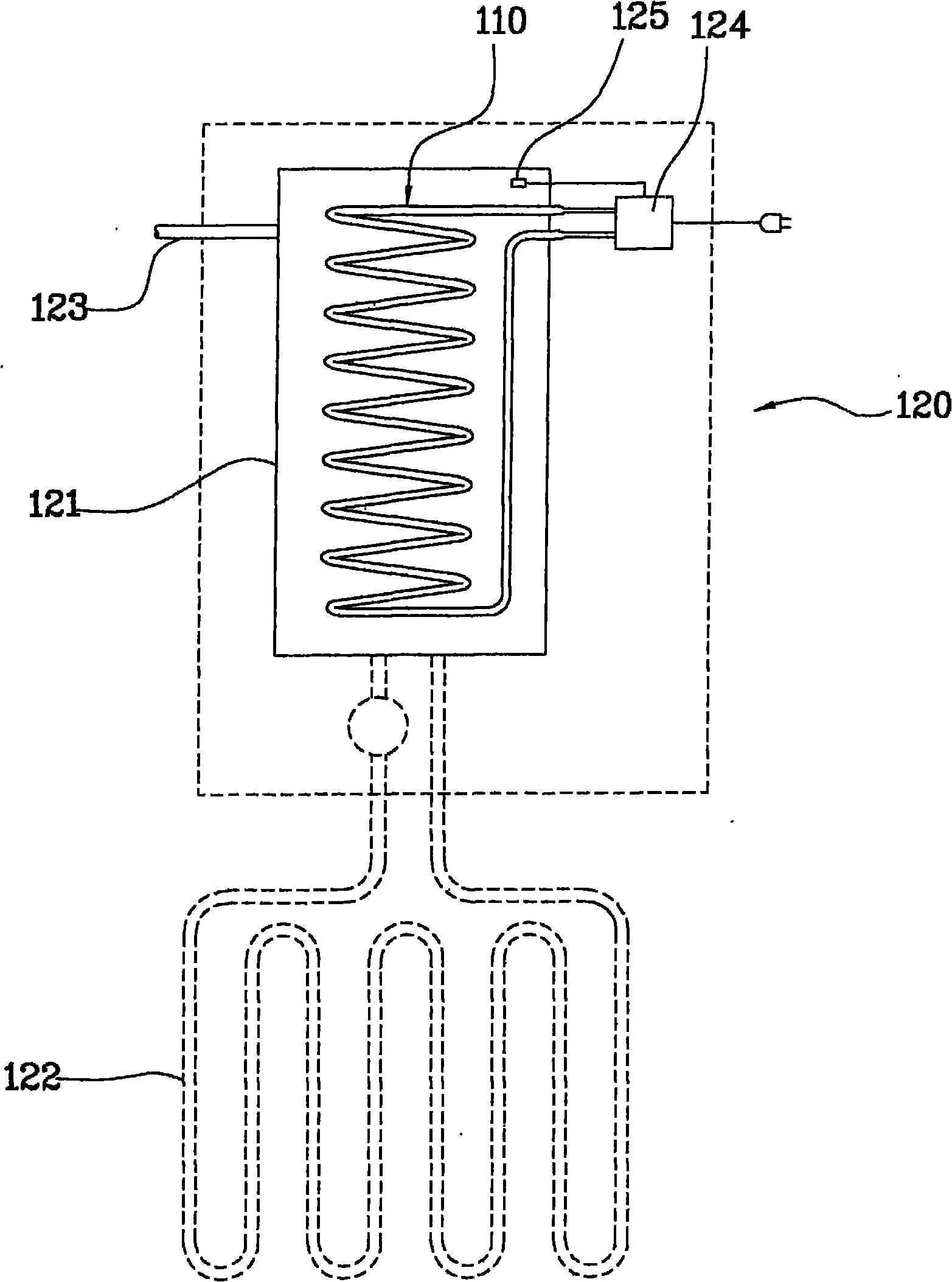
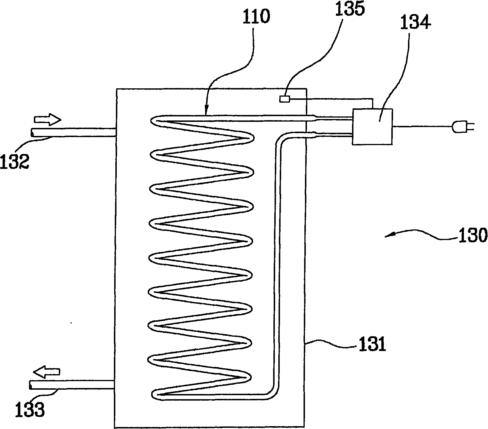
  • Carbon fiber heating source and heating system using the same
  • Carbon fiber heating source and heating system using the same
  • Carbon fiber heating source and heating system using the same

Examples


Embodiment Construction

[0072] The advantages, features and aspects of the present invention will become apparent from the description of the following embodiments with reference to the accompanying drawings. A description of the embodiments will be set forth below.

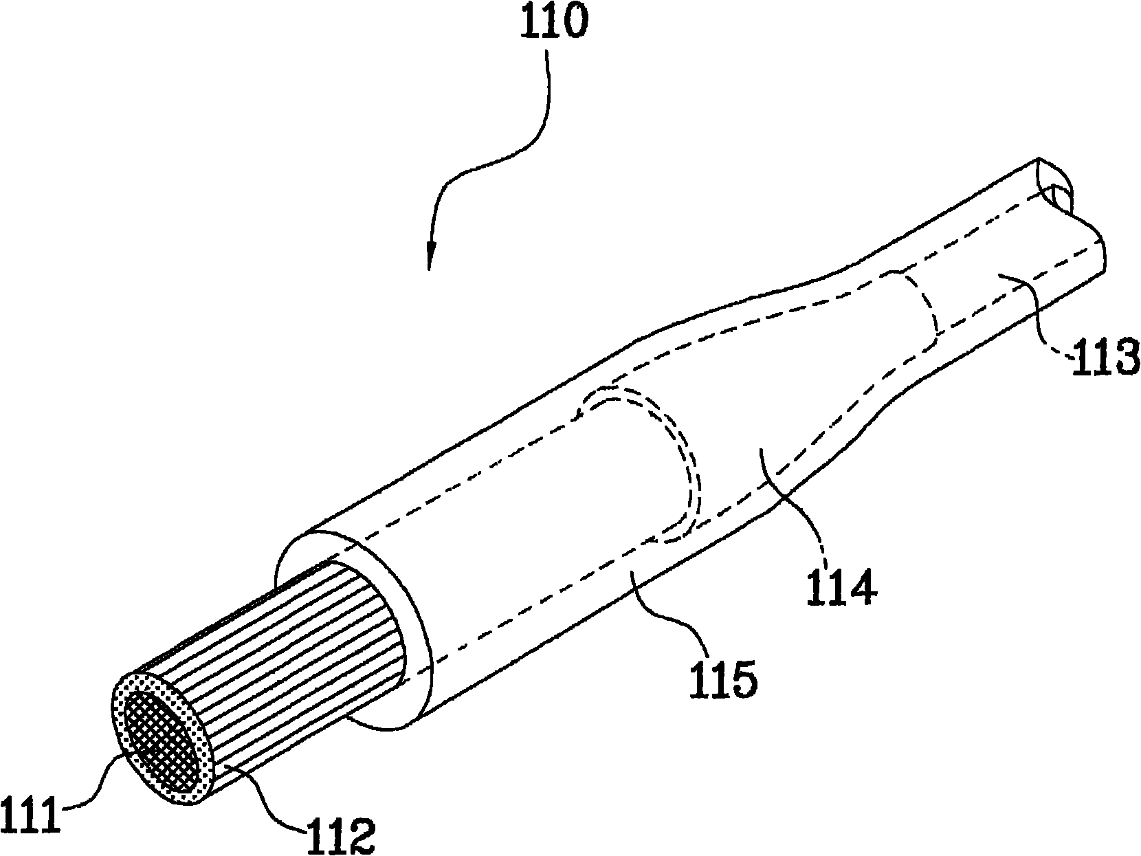
[0073] figure 1 It is a perspective view of a carbon fiber heating source according to an embodiment of the present invention.

[0074] Such as figure 1 As shown, the carbon fiber heating source 110 is formed by a bundle of two or more strands of carbon fiber 111 , and the carbon fiber 111 generates heat at high temperature after power is applied and has a predetermined length. When a bundle of carbon fibers 111 is provided, a predetermined number of glass fibers 112 having the same length are combined with the carbon fibers 111 .

[0075] According to the combination of carbon fiber 111 and glass fiber 112 , glass fiber 112 having high tensile strength against external force including tension or bending force applied to both sides o...


PUM

PropertyMeasurementUnit
thicknessaaaaaaaaaa
melting pointaaaaaaaaaa

Abstract

A carbon fiber heating source includes a bundle of carbon fibers combined with glass fibers. The bundle is surrounded with a silicone coating layer and has high tensile strength responsive to bending and tension while emitting heat at high temperature. The carbon fiber heat emitting source includes heat emitting fibers formed by combining carbon fibers with glass fibers. Connection terminals are formed at both ends of the heat emitting fibers so that electricity can be applied thereto. A coating member coats the surfaces of the heat emitting fibers and the connection terminals. The coating member may be a silicone coating layer formed on the surfaces of heat emitting fibers and contacted with the connection terminals. The heat emitting fibers are obtained by combination of carbon fibers, glass fibers and at lesat a bundle of polyester fibers.

Description

[0001] Cross References to Related Applications [0002] This application claims priority from Korean Patent Application Nos. 10-2009-40478, 10-2009-40483, and 10-2009-40489 filed on May 8, 2009, which are hereby incorporated by reference. technical field [0003] The present invention relates to a high-temperature heating source, in particular to a carbon fiber heating source, which comprises a bundle of carbon fibers (carbon fiber bundles) combined with a predetermined number of glass fibers, wherein the carbon fiber bundles are surrounded by silicon organic Compound coating, and the carbon fiber bundle has high tensile strength to bend, and has tension when heating at high temperature. Background technique [0004] Generally, various heating systems that require high temperature, such as boilers or water heaters, are provided with high-temperature heat sources. This heating system heats water or air to generate hot water or hot air by utilizing the heat emitted or radiat...

Claims


Application Information

Patent Timeline
Patent Type & Authority Applications(China)
IPC IPC(8): H05B3/54F24H9/00
CPCF24H1/202F24D13/024F24H3/0405H05B3/145F24H1/121H05B3/82F24D19/0029Y02B30/00
Inventor 宋英瀚
Owner ECO CARBON ENERGY CO LTD
Learn More