Cable drag chain

A cable and towline technology, applied in the installation of towlines, suspension chains, cables, etc., can solve problems such as poor production efficiency and attenuation of braking effects, and achieve the effects of excellent productivity, easy formation, and simple structure

Inactive Publication Date: 2011-01-19
SHIMA SEIKI MFG LTD
View PDF2 Cites 14 Cited by
  • Summary
  • Abstract
  • Description
  • Claims
  • Application Information

AI Technical Summary

Problems solved by technology

First of all, in the structure of Patent Document 1, there is the following problem: a cushioning member as other parts outside the frame must be prepared, and it must be installed on the frame, and the production efficiency is not good.
In addition, in the structure of Patent Document 2, there is a problem that since the brake is applied by the sliding contact of the frame, the braking effect is attenuated due to wear.

Method used


Image

  • Cable drag chain
  • Cable drag chain
  • Cable drag chain

Examples


Embodiment approach 1

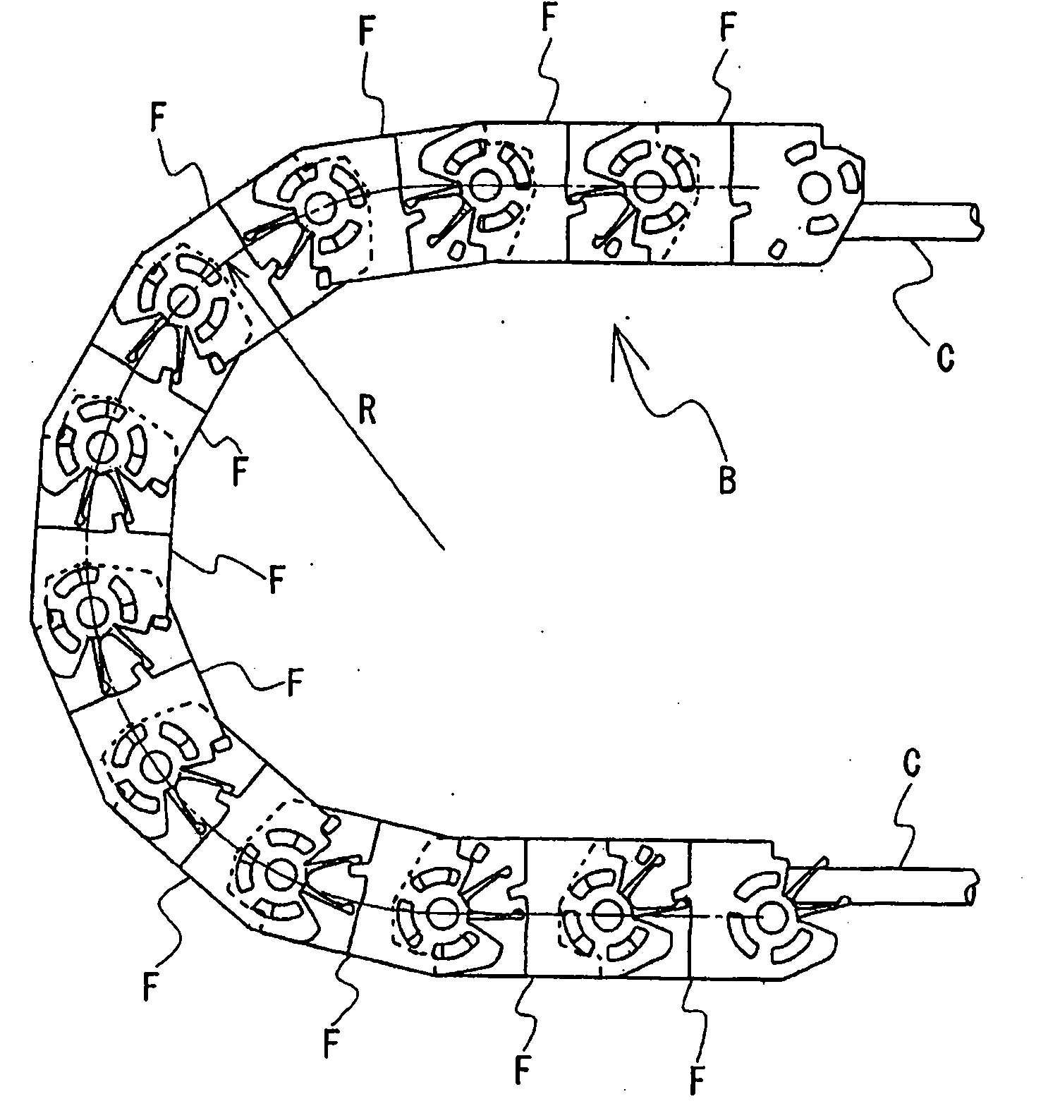
[0036] figure 1 It is a schematic configuration diagram of the cable drag chain of this embodiment. The cable drag chain B guides and protects the cable C for supplying electric power and the like to a moving body. This cable drag chain B is formed by connecting a plurality of frame bodies F flexibly, and the cable C can be arranged in a guide part formed inside the frame body F connected. Generally, the cable drag chain B is used so that at least one of both end parts is connected to a mobile body, and the middle part is folded back in U shape, and the folded-back position moves with the movement of a mobile body. Here, the rotation angle of each frame F constituting the cable chain B with respect to the adjacent frame F is restricted by the rotation angle limiting mechanism, and the cable chain B connecting these frames F cannot bend with a predetermined bending radius (Fig. In the R) below the bending radius bending. Therefore, the cable C arrange|positioned in the cable...

Embodiment approach 2

[0051] Embodiment 2 demonstrates the cable drag chain which used the frame body which provided one elastic protrusion and two receiving parts on one side panel of a frame body. In addition, the same code|symbol as Embodiment 1 is attached|subjected to the same structure as Embodiment 1, and description is abbreviate|omitted.

[0052] Figure 4 It is an explanatory drawing which shows the connection state of the housing|casing which comprises the cable drag chain of this embodiment. On the side panel 1 of the frame body F, an elastic protrusion 55 protruding from the side is formed. In addition, two receiving portions 65 , 66 corresponding to the elastic protrusion 55 are formed. Specifically, the receiving portions 65 and 66 are formed at predetermined intervals on the circumference centered on the shaft portion 11 of the inner portion 10, and when the frames F are connected, the front ends of the elastic protrusions 55 of the adjacent frames F are sandwiched from both sides...

Embodiment approach 3

[0055] In embodiment 3, according to Figure 5 A structure in which the rotation of the housing is braked by friction when the elastic protrusions contact the receiving portion and the elasticity of the elastic protrusions is used to adjust the frictional force will be described.

[0056] Figure 5 It is an explanatory drawing which shows the connection state of the housing used for the cable drag chain of this embodiment. The elastic projections 71 and 72 provided on the frame body F extend outward in the radial direction from the two side edges of the side panel 1 with the shaft hole 21 and the shaft portion 11 as the center respectively, and then form a curved arm shape extending in the circumferential direction. . The bending directions of the elastic protrusions 71 and 72 are both clockwise, and the two elastic protrusions 71 and 72 are approximately point-symmetrical. In addition, the receiving portion 81 corresponding to the elastic protrusion 71 is on the side of th...


PUM


Abstract

Provided is a cable drag chain wherein braking can be applied to frame pivoting, and that furthermore has excellent producibility. The cable drag chain is constructed such that multiple frames (F) are formed coupled to be mutually pivotable, and a long body, such as a cable, is arranged in a guide part enclosed by each frame. The cable drag chain has a construction wherein, between the coupled frames (F1, F2), the pivot angle of the frame (F2) is restricted by contact between a stopper piece 31 (stopper receiver 42) of the one frame (F1) and a stopper receiver (41) (stopper piece 32) of the other frame (F2). The cable drag chain also has a construction wherein elastic projections (51, 52) of the one frame (F2) contact a receiver part (61) of the other frame (F1) when the coupled frames (F) are pivoted, and braking is applied to the relative rotation of the two frames (F1, F2) by the elasticity of the elastic projections (51, 52).

Description

technical field [0001] The invention relates to cable drag chains for guiding and protecting cables, signal lines or compressed air hoses, hydraulic hoses, etc. connected to mobile bodies. Background technique [0002] Power lines, signal lines, or pneumatic hoses, hydraulic hoses, etc. (hereafter collectively referred to as "cables") connected to the moving body, and the part where the bending stress acts in the length direction of the cable moves with the movement of the moving body . Therefore, cables have been guided and protected by cable drag chains so that the cables do not bend excessively. [0003] The cable drag chain is formed by connecting a plurality of frames flexibly to each other, and the cables can be protected by the frames by arranging the cables in the guide portion surrounded by the frames. In addition, a stopper piece and a stopper receiver are provided on each frame, and the connected frames are restricted in rotation angle when the stopper piece of ...

Claims


Application Information

Patent Timeline
Patent Type & Authority Applications(China)
IPC IPC(8): F16G13/16H02G11/00
CPCH02G3/0475F16G13/16
Inventor 下村博则
Owner SHIMA SEIKI MFG LTD
Why Eureka
Try Eureka