
Heartbeat detection method based on cuff device

A detection method and cuff technology, applied in the field of signal processing, can solve the problems of low heart rate detection rate, affecting accuracy, and low user evaluation, and achieve the effect of improving denoising ability and accuracy

Inactive Publication Date: 2011-01-26
张辉 +2
View PDF0 Cites 33 Cited by
  • Summary
  • Abstract
  • Description
  • Claims
  • Application Information

AI Technical Summary

Problems solved by technology

[0006] (1) Most of the existing related patent technologies at home and abroad use chest strap electrodes to collect ECG signals. The main problem of this method is that it is not comfortable to wear, especially not suitable for wearing during sports
At the same time, the chest is prone to sweat during exercise, which will affect the accuracy of detection
Therefore, the chest belt type exercise heart rate signal detection device is difficult to be adopted by most users, thus affecting the popularization and application of the technology
[0007] (2) Some of the existing related patent technologies at home and abroad still use the wrist radial artery pulse measurement method to obtain the heart rate. However, this method has the problems of weak pulse signal and easy deviation of the detection position, which can easily affect the accuracy of heart rate detection. sex
Especially not suitable for heart rate detection during exercise
Weak signals are often submerged in large-amplitude motion noise, and most of the noise caused by motion is non-stationary noise, which makes signal detection more difficult
Lead to low heart rate detection rate and low user evaluation
Therefore, the wrist radial artery acquisition method is not suitable for heart rate detection during exercise

Method used


Image

  • Heartbeat detection method based on cuff device
  • Heartbeat detection method based on cuff device
  • Heartbeat detection method based on cuff device

Examples


Embodiment Construction

[0032] In order to make the purpose, content, and advantages of the present invention clearer, the following further describes the embodiments of the present invention in detail with reference to the accompanying drawings.

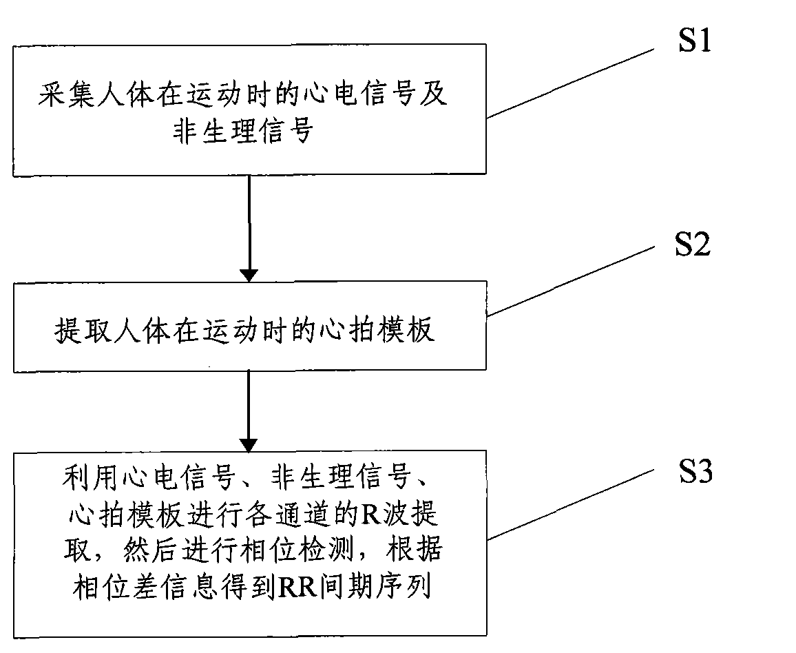
[0033] The method flow chart of the present invention is as figure 1 As shown, including the following steps:

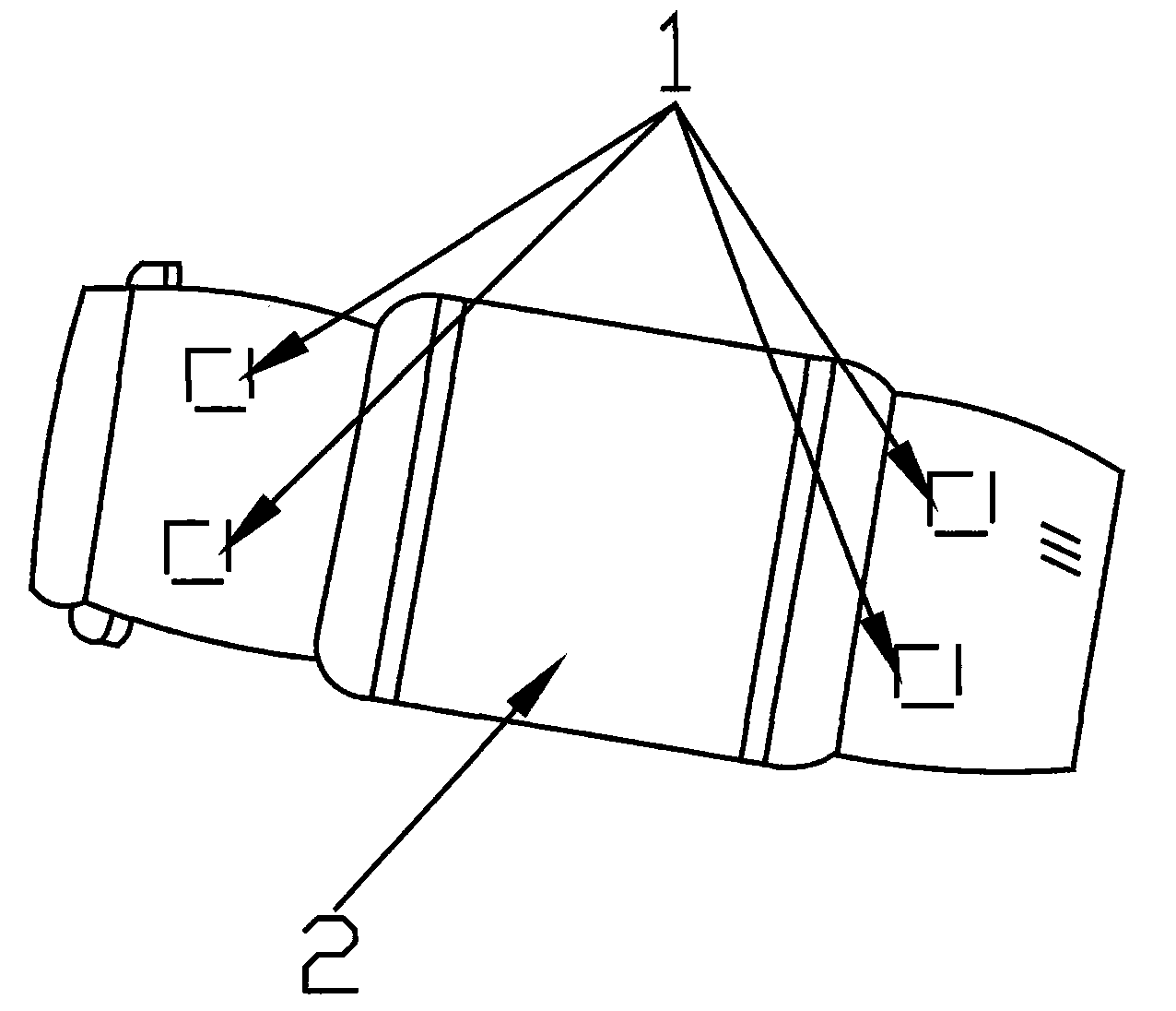
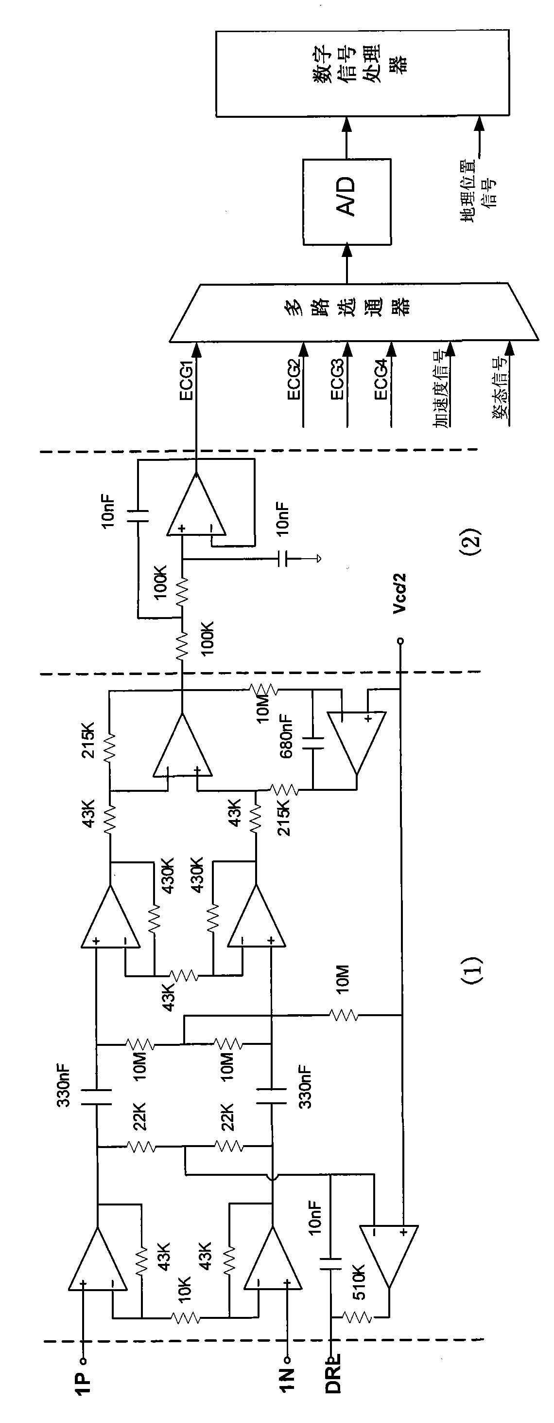
[0034] S1, multi-mode multi-channel signal acquisition. The specific steps are as follows: Wear a cuff device (such as figure 2 As shown), it is a device that uses sensors to collect the following signals and can be worn on the human arm: ECG signal (source of heart rate signal), motion acceleration signal (for ECG signal correction to remove motion artifacts, etc.) Body motion noise), motion posture signal (for ECG signal correction to remove motion artifacts and other body motion noise), and geographic location signals. The signal obtained by the sensor will be converted into a digital signal through the amplifying circuit, filter circuit and A / D ...


PUM


Abstract

The invention discloses a heartbeat detection method based on a cuff device, which comprise the following steps of: S1, collecting electrocardio-signals and non-physical signals of a moving human body, the non-physical signals comprising acceleration signals, posture signals and geographic location signals of a human body, and wherein utilizing electrocardio-electrodes with plurality of passages to collect electrocardio-signals; S2, extracting the heart clap template of a moving human body; S3, carrying out R-wave extraction of each passage by using the collected electrocardio-signals, the non-physical signals and the heart clap template to obtain a R-wave sequence; S4, and carrying out phase detection to the electrocardio-signals of each passage to obtain the phase differences of each passage with time change because of the position of the electrodes, obtaining the RR interphase sequence according to the information of the phase differences so as to obtain heartbeat signals. The method has the advantages of high accuracy and strong noise removing capacity.

Description

Technical field [0001] The invention relates to the technical field of signal processing, in particular to a heart rate detection method based on a cuff device. Background technique [0002] As people’s quality of life has improved, so has the importance of health. Sports and fitness exercises have become important means to prevent diseases, change lifestyles, and improve the quality of life. During exercise and fitness, real-time monitoring of the physiological state of the human body during exercise is a necessary measure to ensure exercise safety. Human body information during exercise includes physiological information and non-physiological information. [0003] Physiological information includes heart rate, myoelectricity, and skin impedance. Non-physiological information is mainly movement information, including movement speed, acceleration, distance, posture and geographic location information. The heart rate in physiological information is an important indicator. Heart...

Claims


Application Information

Patent Timeline
IPC IPC(8): A61B5/0245
Inventor 张辉张力李全政
Owner 张辉
Learn More