Automatic sleeve demoulding mechanism

An automatic demoulding and casing technology, which is applied in the field of molds for manufacturing parts, can solve the problems of high labor intensity and slow speed

Inactive Publication Date: 2011-01-26
GEM YEAR IND
View PDF9 Cites 3 Cited by
  • Summary
  • Abstract
  • Description
  • Claims
  • Application Information

AI Technical Summary

Problems solved by technology

For injection molded parts with internal threads, the threaded mandrel is usually manually unscrewed from the injection molded parts after injection molding. This method i...

Method used


Image

  • Automatic sleeve demoulding mechanism
  • Automatic sleeve demoulding mechanism
  • Automatic sleeve demoulding mechanism

Examples


Embodiment Construction

[0011] The present invention will be further described below by way of examples.

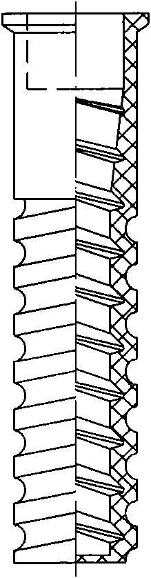
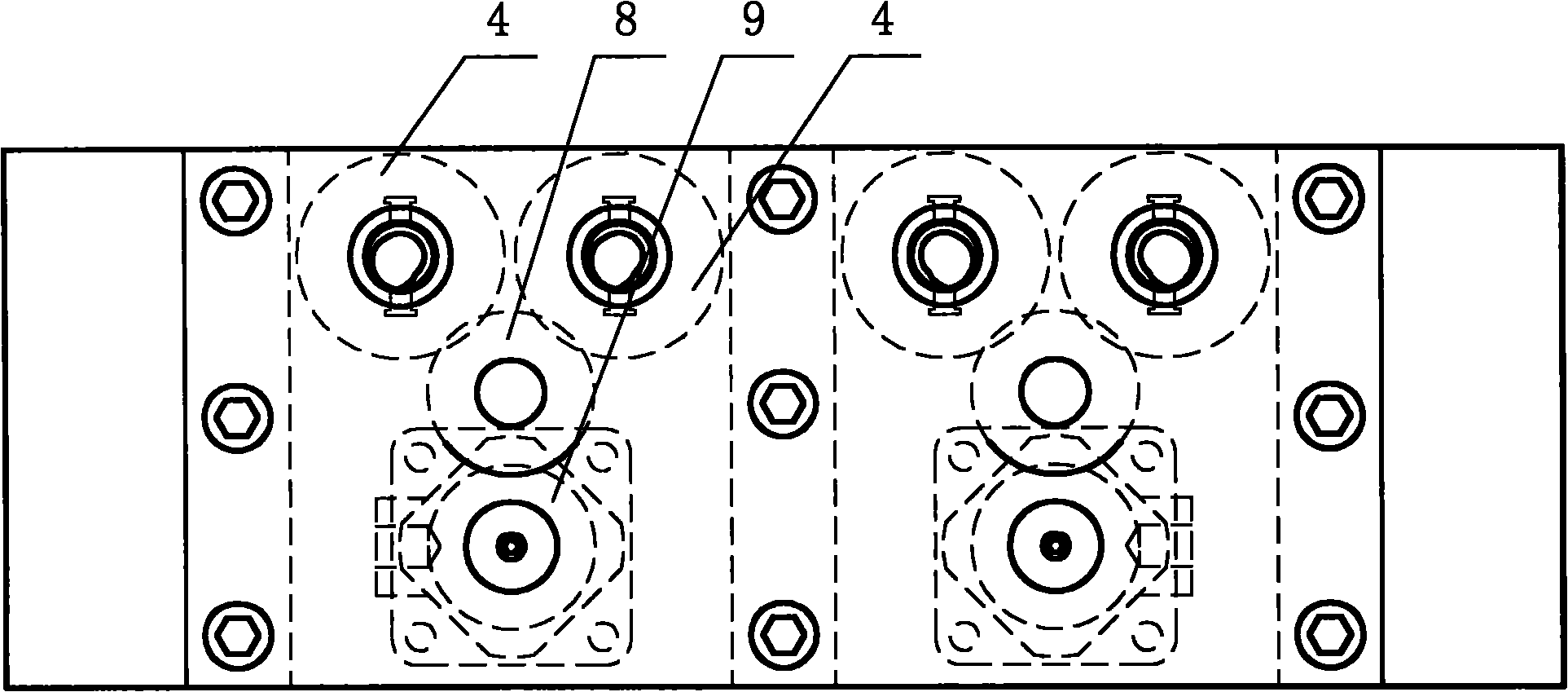
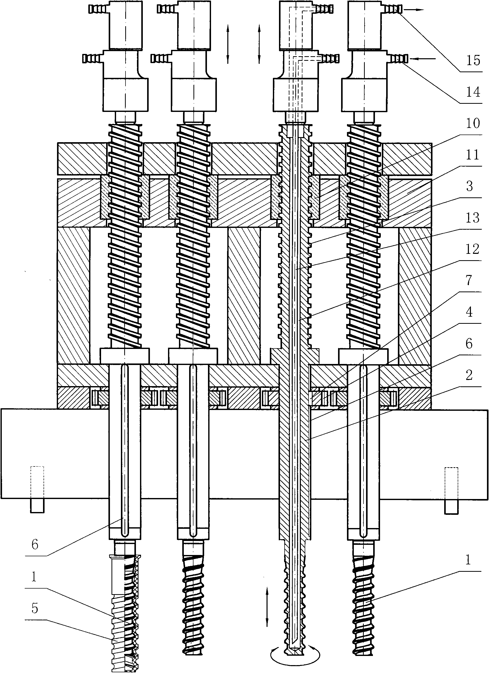
[0012] figure 2 , image 3 It is a schematic diagram of the structure of the automatic demoulding mechanism of four sets of sleeves. As can be seen from the figure, it includes a mandrel 1, on which a connecting shaft 2 and a screw 3 integral with the mandrel 1 are formed, the connecting shaft 2 is covered with a gear 4, and the connecting shaft 2 is equipped with a The keyway 6 in the depth of the inner hole of the tube 5, the gear 4 is connected to the connecting shaft 2 through the key 7 installed in the keyway 6, the connecting shaft 2 and the gear 4 can move relatively axially, the gear 4 meshes with the rotating transmission gear 7, and the transmission gear 8 Driven by the speed reduction device 9, a nut 10 matched with the screw rod 3 is screwed on the screw rod 3, and the pitch of the screw rod 3 is the same as that of the internal thread of the casing 5. Gear 4, nut 10 are fixed on...


PUM


Abstract

The invention discloses an automatic sleeve demoulding mechanism, and aims to provide the automatic sleeve demoulding mechanism, which has the characteristics of simple structure, convenient manufacture and use, continuous production, and rapidness. The automatic demoulding mechanism comprises a mandril and is characterized in that: the mandril is provided with a connecting shaft and a screw which are connected with the mandril integrally; a gear is sleeved on the connecting shaft; the connecting shaft is provided with a key slot which is greater than the depth of the inner hole of the sleeve; the gear is connected with the connecting shaft through a key arranged in the key slot; the connecting shaft and the gear are moved relative to the axial direction; the gear is engaged with a rotary drive gear; a nut which is matched with the screw is screwed on the screw to form a screw pair structure; and the gear and the nut are respectively fixed on a machine frame. The automatic demoulding mechanism has the characteristics of ingenious design, novel structure, high demoulding speed, high quality, and high demoulding efficiency when the drive gear is engaged with a plurality of groups of automatic sleeve demoulding mechanisms, and is suitable for injection-molding, machining and demoulding of large-batch sleeves.

Description

technical field [0001] The invention relates to a mold for manufacturing parts in railway engineering, and more specifically relates to an automatic demoulding mechanism for casings. Background technique [0002] In order to position and fix the rails at the specified positions during railway laying, ensure a fixed gauge of 1435±1mm and a standard height from the top surface of the rail to the platform of the rail. Bury the pre-embedded casing on the subgrade beside the rail, and fix the pre-embedded casing on the steel structure before pouring concrete. Place the elastic backing plate, iron backing plate, under-rail backing plate (rubber), 60kg / m steel rail and insulating block in order from top to bottom. The insulating block is placed between the rail and the shoulder of the iron backing plate, and the angular direction of the insulating block Partially press the back of the rail leg. Finally, put the elastic bars on the iron backing plate and insulating block, fix them...

Claims


Application Information

Patent Timeline
IPC IPC(8): B29C33/44B29C45/40
Inventor 周子雄
Owner GEM YEAR IND
Why Eureka
Try Eureka