Sludge removing structure in large ship ballast water tank

It is a large-scale technology for ship ballast water, which is used in the cleaning equipment of ship tanks, oil tankers, special-purpose ships, etc. It can solve the problems of inability to carry and wash away silt, poor lateral flow performance, etc., and reduce labor. Strength, the effect of improving economic efficiency

Active Publication Date: 2011-01-26
NANTONG COSCO KHI SHIP ENG
View PDF5 Cites 10 Cited by
  • Summary
  • Abstract
  • Description
  • Claims
  • Application Information

AI Technical Summary

Problems solved by technology

[0003] The longitudinals of the double bottom outer plates of the existing ballast tanks generally have only two or so water flow holes within the range of each ...

Method used


Image

  • Sludge removing structure in large ship ballast water tank
  • Sludge removing structure in large ship ballast water tank
  • Sludge removing structure in large ship ballast water tank

Examples


Embodiment Construction

[0013] The specific embodiment of the present invention will be further described below in conjunction with accompanying drawing:

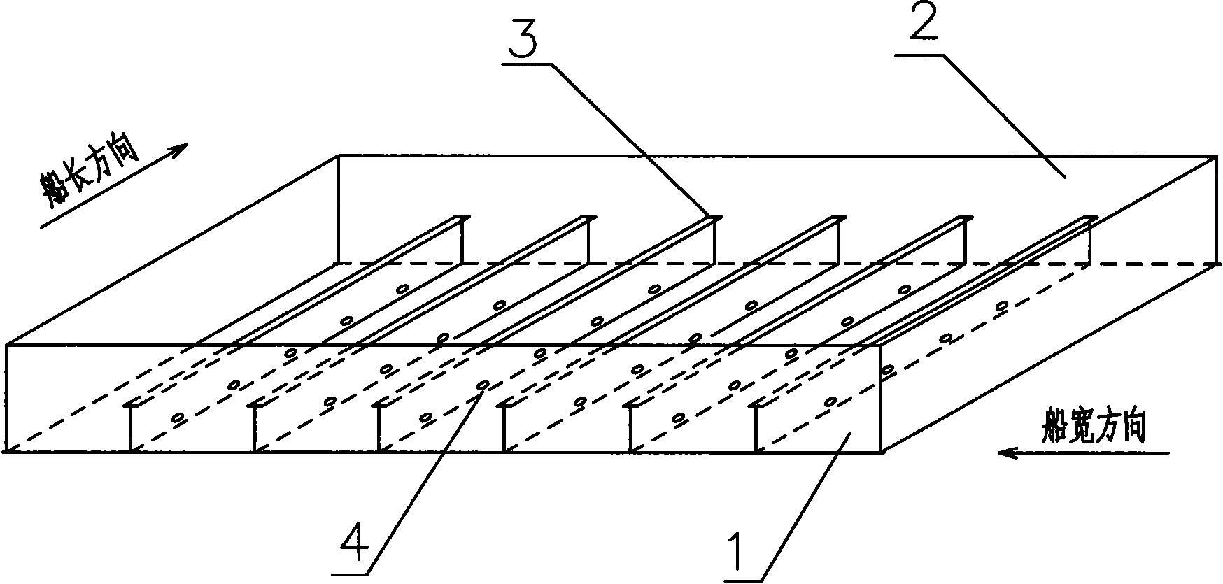
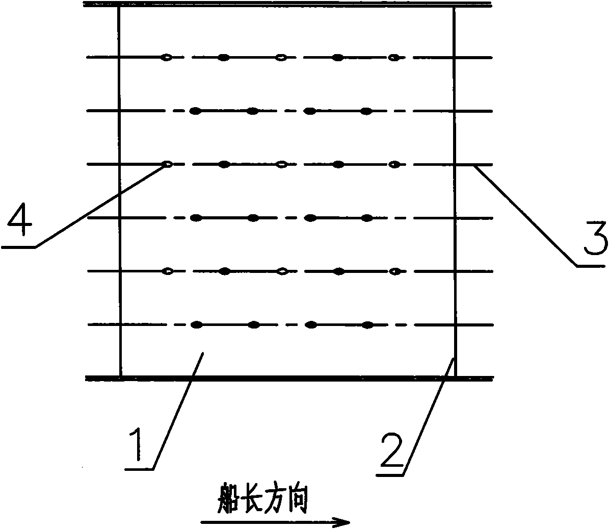
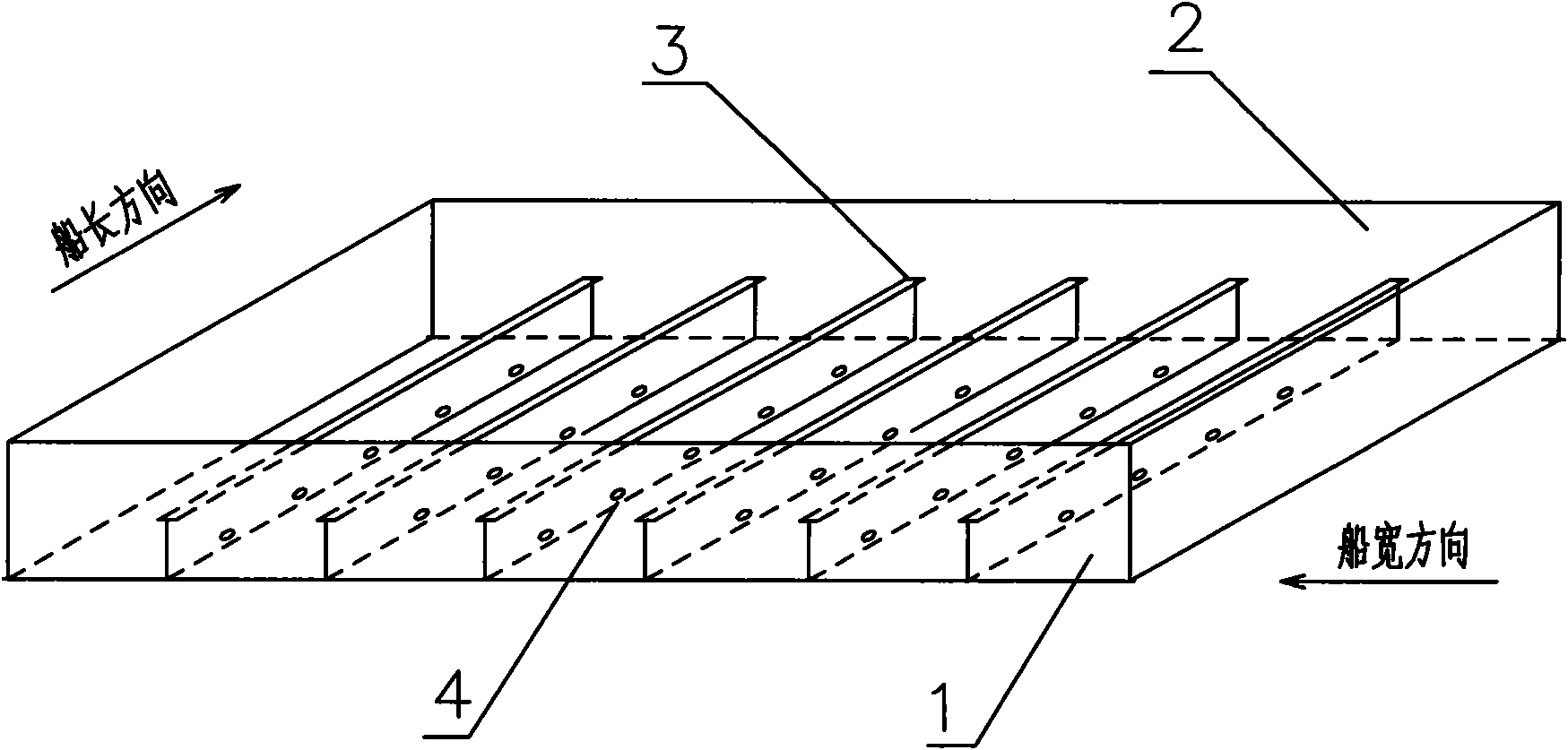
[0014] Such as figure 1 and 2 Shown: a desilting structure in a ballast tank of a large ship, including a bottom plate 1, ribs 2, longitudinals 3 and flow holes 4, and the bottom plate 1 is arranged in parallel and at equal intervals along the width of the ship There are a plurality of ribs 2, and a plurality of longitudinals 3 are arranged between the adjacent ribs 2 along the length direction of the ship in parallel and at equal intervals, and a plurality of water holes 4 at equal intervals are arranged on the longitudinals 3, and The flow holes 4 on the adjacent longitudinals 3 are arranged in a misplaced position, that is, the flow holes 4 on the adjacent longitudinals 3 are not on the same cross section.

[0015] Within the range of each rib position, 4 and 5 flow holes 4 are respectively set on the adjacent longitudinals 3, and the misalig...


PUM


Abstract

The invention discloses a sludge removing structure in a large ship ballast water tank, comprising a ship bottom plate, rib plates, longitudinal keels and water flowing holes, wherein a plurality of rib plates are arranged in parallel on the ship bottom plate at equal intervals along the width direction of the ship; a plurality of longitudinal keels are arranged in parallel between adjacent rib plates at equal intervals along the length direction of the ship; and the longitudinal keels are provided with a plurality of water flowing holes at equal intervals, and the water flowing holes on the adjacent longitudinal keels are staggered, i.e. the water flowing holes on adjacent longitudinal keels are not on the same cross section. The invention effectively clears sludge accumulated in a ballast tank, lightens the labor intensity of clearing the sludge of crews and improves the economic benefit of ship operation.

Description

technical field [0001] The invention relates to the field of shipbuilding, in particular to a desilting structure in a ballast water tank of a large ship. Background technique [0002] Large ships often berth at ports such as Ningbo, Zhoushan, and Shanghai, where the seawater has an extremely high sediment concentration. Large ships have to ballast tens of thousands of tons of turbid seawater in this area every voyage, and tens or even hundreds of tons of silt will be deposited in the ballast tanks of each voyage, and it is difficult for these silts to be discharged to the ship with the ballast water. outside. Accumulated over time, the silt in the cabin will reach the height of the bottom skeleton after a few years, reducing the loading capacity by about thousands or even tens of thousands of tons. The location of the silt accumulation can no longer inspect the ship's structure for defects such as corrosion, corrugation, buckling or fractures. While reducing the ship's l...

Claims


Application Information

Patent Timeline
IPC IPC(8): B63B57/02
Inventor 薛国良潘志远井上幸也沈亚明孙启荣
Owner NANTONG COSCO KHI SHIP ENG
Why Eureka
Try Eureka