Supercharge Your Innovation With Domain-Expert AI Agents!

Rotary bin for vacuum continuous coating production line

A coating production line and vacuum technology, applied in the field of rotary silo, can solve the problems of multiple vacuum equipment, high cost, long production line, etc., and achieve the effect of reducing vacuum equipment, saving cost and shortening production line

Active Publication Date: 2011-01-26
湖南玉丰真空科学技术有限公司
View PDF6 Cites 1 Cited by
  • Summary
  • Abstract
  • Description
  • Claims
  • Application Information

AI Technical Summary

Problems solved by technology

[0002] At present, the existing mechanical continuous processing equipment is basically arranged in a straight line along the same direction, and the production line is relatively long. Especially in the production of vacuum continuous coating process, more vacuum equipment is required, so that the cost of production equipment is higher.

Method used


Image

  • Rotary bin for vacuum continuous coating production line
  • Rotary bin for vacuum continuous coating production line
  • Rotary bin for vacuum continuous coating production line

Examples


Embodiment 1

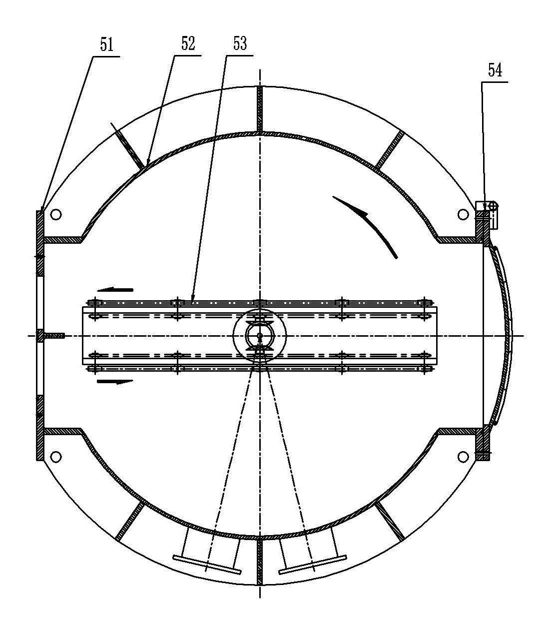
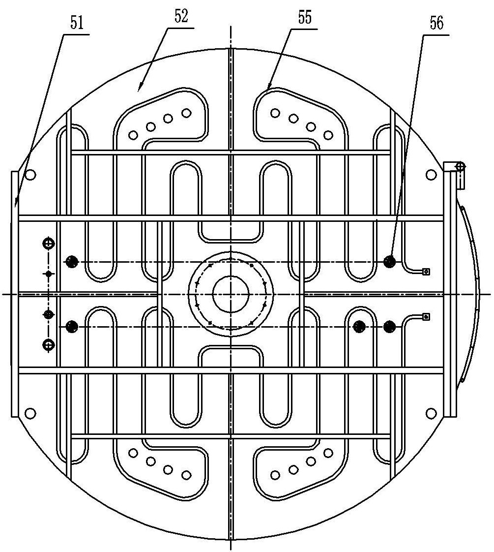
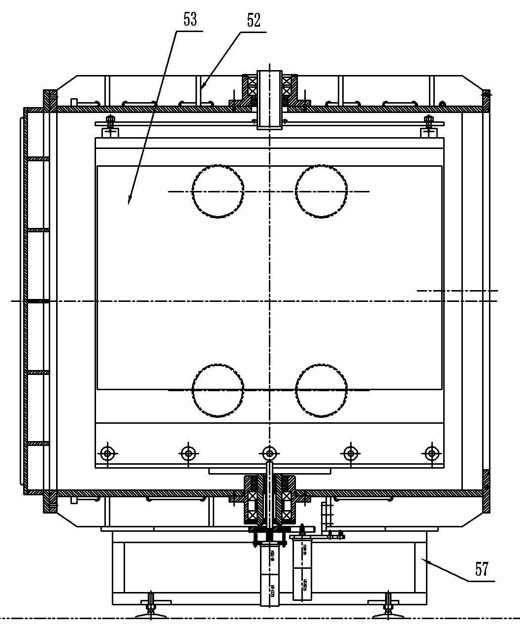
[0026] Embodiment 1, the present invention includes a bin body 52, a revolving bin door frame 51, a positioning device 56, and a rotary mechanism 53. The bin body 52 is fixedly mounted on a bin body frame 57, and a revolving bin door frame is arranged on one side of the bin body 52. 51. A rotary mechanism 53 compatible with the inner chamber of the container body 52 and a positioning device 56 matched with the rotary mechanism 53 are arranged in the bin body 52 . For the convenience of maintenance and observation, a sealed detection door 54 can also be arranged on one side of the bin body 52; One side of the warehouse body side wall water pipe 59 is provided, or the warehouse top water pipe 55 and the warehouse body side wall water pipe 59 are set at the same time; for the convenience of connection with the production equipment, the warehouse body connection door cover can also be installed on the outside of the rotary warehouse door frame 51 58, the connecting door cover 58 c...

Embodiment 2

[0033] Embodiment 2, for the convenience of heating the workpiece, the present invention can also install a heater 4 in the rotating frame 3 . refer to Figure 1 to Figure 9 , all the other are with embodiment 1.

Embodiment 3

[0034] Embodiment 3, the lower part of the lower rotating shaft 23 of the present invention can also be equipped with a pulley A, and the pulley A is connected with the pulley B of the rotary driving device, so as to realize rotation through a belt drive. Apparently, in the present invention, the lower part of the lower rotating shaft 23 can also be connected with the rotary cylinder, so as to realize the rotation through the transmission of the rotary cylinder. refer to Figure 1 to Figure 9 , and the rest are the same as the above-mentioned embodiment.


PUM


Abstract

The invention discloses a rotary bin for a vacuum continuous coating production line, which mainly aims to solve the technical problem of long production lines and high cost and the like existing in current continuous processing equipment. The rotary bin of the invention comprises a bin body, a rotary bin doorframe, a position-measuring device and a rotary mechanism, wherein the bin body is fixed on a bin frame, one side of the bin body is provided with the rotary bin doorframe, and the rotary mechanism matched with the inner cavity of the bin body and the position-measuring device matched with the rotary mechanism are arranged in the bin body; meanwhile, one side of the bin body also can be provided with a detecting gate; or the top of the bin body is provided with a bin-top pipe; or one side of the bin body is provided with a bin sidewall pipe; or the outer side of the rotary bin doorframe is connected with a bin connecting door pocket; the rotary mechanism comprises upper transmission magnetic fluid, lower transmission magnetic fluid, a rotating frame, a lower support flange and an upper support flange, wherein the upper transmission magnetic fluid and the lower transmission magnetic fluid are vertically and symmetrically arranged on the same axis, a lower rotating shaft is hermetically arranged in the lower transmission magnetic fluid, and the lower end of the lower rotating shaft is provided with a rotary driving device. In the invention, two work rests can be controlled to realize 180-degree U-turn operation so as to return the workpieces to the production line to carry put processing continuously. The rotary bin of the invention is particularly suitable to be used in the production process of a vacuum production line, thereby reducing about half of vacuum equipment and saving the cost.

Description

technical field [0001] The invention relates to a rotary chamber used in a vacuum continuous coating production line. Background technique [0002] At present, the existing mechanical continuous processing equipment is basically arranged in a straight line along the same direction, and the production line is relatively long. Especially in the production of vacuum continuous coating process, more vacuum equipment is needed, so that the cost of production equipment is higher. Contents of the invention [0003] The object of the present invention is to provide a rotary chamber for a vacuum continuous coating production line which has a simple structure, can reduce vacuum equipment and shorten the production line. [0004] The technical solution adopted by the present invention to solve its technical problems is: it includes a warehouse body 52, a rotary warehouse door frame 51, a position measuring device 56 and a rotary mechanism 53, the warehouse body 52 is fixedly installe...

Claims


Application Information

Patent Timeline
IPC IPC(8): C23C14/56C23C16/54
Inventor 舒逸李国强
Owner 湖南玉丰真空科学技术有限公司
Features
  • R&D
  • Intellectual Property
  • Life Sciences
  • Materials
  • Tech Scout
  • Unparalleled Data Quality
  • Higher Quality Content
  • 60% Fewer Hallucinations
Learn More