Defrosting heater, evaporator assembly of refrigerating equipment and refrigerator with same

A defrosting heater and refrigeration equipment technology, applied in refrigeration components, lighting and heating equipment, evaporators/condensers, etc., can solve the adverse effects of wiring harness and box gallbladder, the temperature rise on the side of the evaporator, and the defrosting residual ice problems such as secondary freezing, to achieve the effect of increasing fixing reliability, preventing ice blockage, and avoiding secondary freezing

Active Publication Date: 2011-01-26
HEFEI MIDEA REFRIGERATOR CO LTD +1
View PDF6 Cites 17 Cited by
  • Summary
  • Abstract
  • Description
  • Claims
  • Application Information

AI Technical Summary

Problems solved by technology

In the existing L-shaped double-pipe structure defrosting heater, its pipeline is parallel to the bottom surface of the evaporator. Since the drain of the water receiving pan is far away from the heater, the heat received during defrosting is less, which may easily cause the residual ice in the defrosting period. Secondary freezing of the water receiving tray and the drain outlet will block the drain outlet or cause defrosting water to overflow
[0004] In addition, in order to facilitate the bending and fixing of the heating tube, the right-angled bending part of the above-mentioned L-shaped double-tube heater usually protrudes upwards for a section. Since the heating wire is arranged in the heating tube, the temperature rise on the side of the evaporator is likely to be too fast and too high during defrosting. High, causing adverse effects on wiring harnesses and tanks, etc.

Method used


Image

  • Defrosting heater, evaporator assembly of refrigerating equipment and refrigerator with same
  • Defrosting heater, evaporator assembly of refrigerating equipment and refrigerator with same
  • Defrosting heater, evaporator assembly of refrigerating equipment and refrigerator with same

Examples


Embodiment Construction

[0036] Embodiments of the present invention are described in detail below, examples of which are shown in the drawings, wherein the same or similar reference numerals designate the same or similar elements or elements having the same or similar functions throughout. The embodiments described below by referring to the figures are exemplary only for explaining the present invention and should not be construed as limiting the present invention.

[0037] In the description of the present invention, the orientation or positional relationship indicated by the terms "inner", "outer", "upper", "lower" and "bottom" are based on the orientation or positional relationship shown in the drawings, and are only for convenience The invention is described without requiring that the invention must be constructed and operated in a particular orientation, and thus should not be construed as limiting the invention.

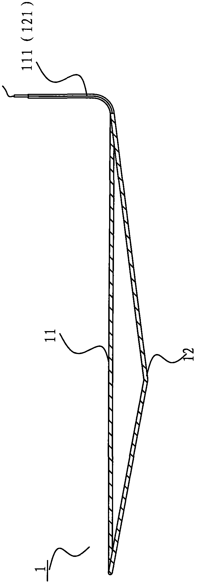
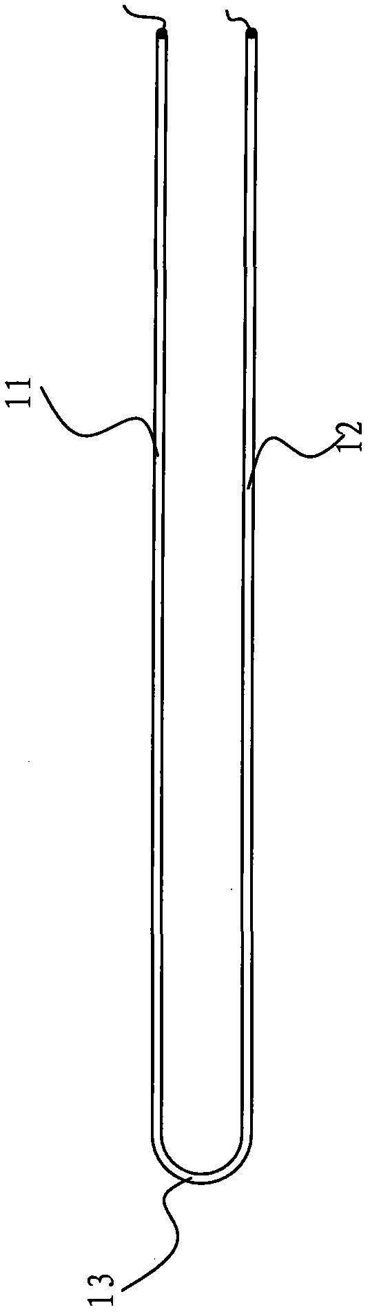
[0038] First refer to the following Figure 1-Figure 2 A defrost heater 1 of a r...


PUM


Abstract

The invention discloses a defrosting heater. The defrosting heater is suitable for being arranged at an evaporator of refrigerating equipment and between water collecting disks under the evaporator. The defrosting heater comprises a first heating pipe, a second heating pipe and a connecting pipe, wherein the first heating pipe is suitable for being close to the bottom surface of the evaporator and parallel to the bottom of the evaporator; both ends of the second heating pipe are respectively inclined to the middle along the direction from the bottom surface of the evaporator to drainage openings of the water collecting disks; and the connecting pipe is in a U shape and is used for connecting the first ends of the first heating pipe and the second heating pipe. The defrosting heater of the embodiment of the invention prevents the secondary freezing of defrosted residual ice at the water collecting disks and the drainage openings so as to solve the problem of drainage opening blockage or defrosting water overflow. The invention also discloses an evaporator assembly of refrigerating equipment with the defrosting heater and a refrigerator with same.

Description

technical field [0001] The invention relates to the field of refrigeration equipment, in particular to a defrosting heater, an evaporator assembly of the refrigeration equipment having the defrosting heater and a refrigerator having the same. Background technique [0002] When the air-cooled refrigerator is cooling, the fan is used to make the cold air forced convection cycle to indirectly refrigerate and freeze the food. The water evaporated from the food in the refrigerator is taken away by the cold air and freezes on the fins and pipe surface of the evaporator when it passes through the evaporator. Form a layer of frost. The existence of the frost layer will affect the heat exchange of the evaporator, make the refrigeration performance of the air-cooled refrigerator worse, and even block the circulation of the air, resulting in failure. In order to ensure the normal operation of the air-cooled refrigerator, the surface of the finned evaporator needs to be defrosted regul...

Claims


Application Information

Patent Timeline
Patent Type & Authority Applications(China)
IPC IPC(8): F25D21/06F25B39/02F25B11/02
Inventor 方忠诚任伟李凌云阚爱梅
Owner HEFEI MIDEA REFRIGERATOR CO LTD
Why Eureka
Try Eureka