Spent fuel defect detecting system

A technology for defect detection and waste fuel, which is applied in fuel oil testing, material inspection products, and analysis of materials, etc.

Active Publication Date: 2014-02-12
KEPCO NUCLEAR FUEL CO LTD
View PDF4 Cites 0 Cited by
  • Summary
  • Abstract
  • Description
  • Claims
  • Application Information

AI Technical Summary

Problems solved by technology

[0005] For example, the detection device is generally installed in a deep pit (Pit) at a depth of 5m from the nuclear waste storage tank of the power station. There is no detection device in use at present. In the absence of a clear cause of defective fuel and countermeasures, It is temporarily stored in the storage tank of the power station alone, so a safe permanent measure for judging whether it is defective fuel or not is required

Method used


Image

  • Spent fuel defect detecting system
  • Spent fuel defect detecting system
  • Spent fuel defect detecting system

Examples


Embodiment Construction

[0022] Hereinafter, a spent fuel defect detection system (hereinafter referred to as a detection system Sipping System) according to an embodiment of the present invention will be described with reference to the drawings.

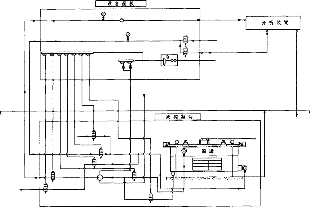
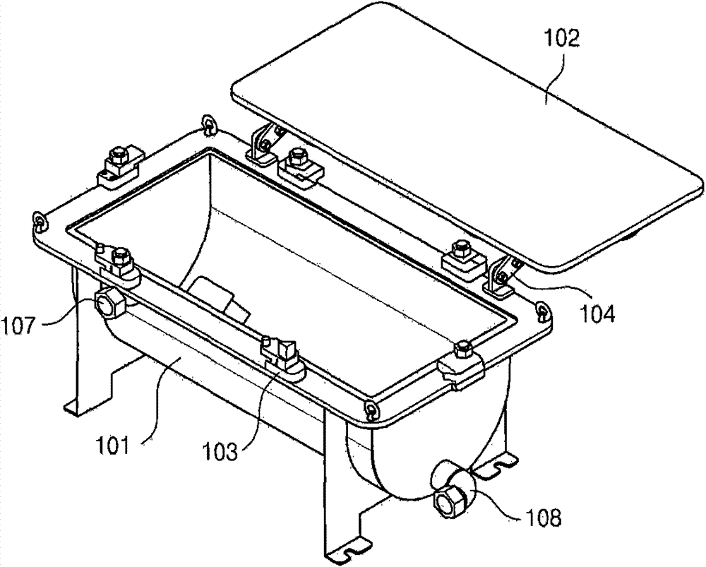
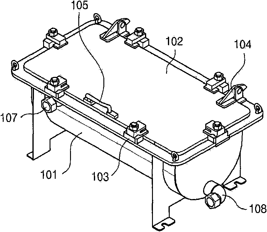
[0023] figure 1 It is a perspective view showing the overall structure of the system of the present invention, and Fig. 2 shows figure 1 The oblique view of the cylinder tank (canister) involved, Figure 3 is a representation figure 1 The oblique view of the valve console (ValveConsole) involved, Figure 4 is a representation figure 1 The oblique view of the involved equipment panel (Euipment Panel), Fig. 5 shows figure 1 Oblique view of the Operating Box involved.

[0024] figure 1 The overall structure of the detection system involved in this embodiment is shown.

[0025] Accordingly, the detection system of this embodiment is used in the detection of nuclear waste, and is installed in the nuclear waste storage tank of the nuclear power plant for heavy...


PUM


Abstract

PURPOSE: By safeing and rapidly advancing the test process of the nuclear fuel the use after-edge flaw detection system improves the safety of the Atomic Electrical Power Plant equipment. CONSTITUTION: In the inside which canister is shut tightly with cover, the fuel is stored after use after use in the coke weighing hopper floor. The valve cone brush has the MC type pickup bolt for pulling up canister, and the pump and the valve sending the nuclide sample to the reservoir outside. The equipment panel is installed outside reservoir(100).

Description

technical field [0001] The invention relates to nuclear waste of heavy water furnaces, in particular to a system capable of soundness detection in time when an abnormality occurs in the nuclear waste. Background technique [0002] In general, nuclear fuel assemblies for heavy water furnaces include: uranium sintered bodies that generate heat through nuclear fission; fuel rods that house the sintered bodies in zirconium alloy cladding tubes; rod end joint plates that support both sides of the nuclear fuel assembly; sealed fuel rods Rod end caps at both ends; supports connected to fuel rods; spacers, etc. [0003] However, in the process of handling the nuclear fuel assembly inside the atomic furnace, defects may occur on the assembly due to interference between adjacent fuels or structures, etc., and such defects are also caused by the manufacturing process or improper design of the nuclear fuel. Therefore, in a nuclear power plant, a detection device capable of detecting fu...

Claims


Application Information

Patent Timeline
Patent Type & Authority Patents(China)
IPC IPC(8): G01N33/22G01N23/00G01N1/02
CPCY02E30/30G21C17/06
Inventor 朴锺烈崔昌范禹尚均金龙赞
Owner KEPCO NUCLEAR FUEL CO LTD
Why Eureka
Try Eureka