Polymer actuator, valve and shaft seal structure using the same
An actuator, polymer technology, applied in piezoelectric/electrostrictive/magnetostrictive devices, piezoelectric effect/electrostrictive or magnetostrictive motors, valve devices, etc., can solve the complex internal structure and other problems, to achieve excellent performance, prevent internal deterioration, and suppress the effect of failure.
- Summary
- Abstract
- Description
- Claims
- Application Information
AI Technical Summary
Problems solved by technology
Method used
Image

Examples
Embodiment 1
[0139] Hereinafter, embodiments of the polymer actuator in the present invention will be described. In this example, in order to confirm whether the deformation method of the electro-stimulating polymer material that deforms at a site other than the site when an electrical external stimulus is applied can be used in a polymer actuator, a predetermined voltage was applied and the measurement was performed The amount of displacement. by Figure 13 The displacement measuring device 75 shown performs this measurement.
[0140] The displacement measuring device 75 has a frame 77 for fixing an electrically irritating polymer material (gel sheet of human muscle (registered trademark), product number H0-1) 76, and the frame 77 Mobile mobile station 78. In addition, a high-voltage power supply (manufactured by Matsuda Preeision Co., Ltd., model HJPQ-30P1) 79 is provided. The high-voltage power supply 79 is connected to a fixed electrode (not shown) sandwiching the object 76 to be measur...
Embodiment 2
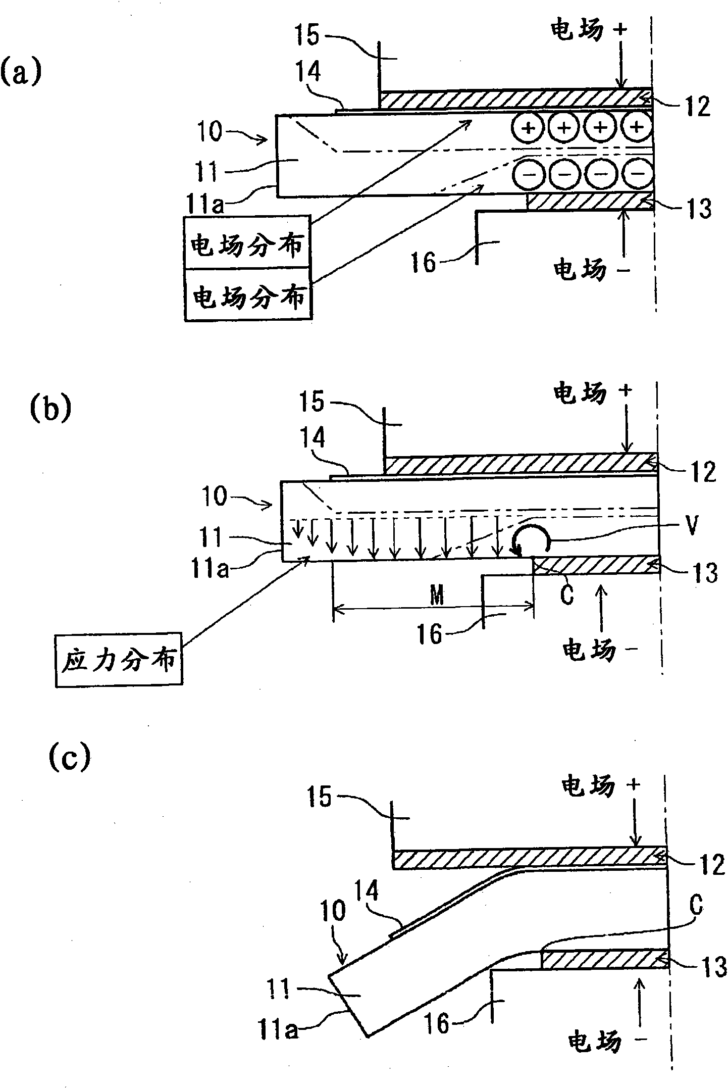
[0149] The distribution of the electric field vector when a voltage is applied to the polymer actuator of the present invention was analyzed by simulation. For comparison, against Figure 30 The shown structure of the shaft seal part, that is, the polymer material (shaft seal body) 1 sandwiched by the fixed electrode part with the same application area, is also simulated, and the polymer material 1 is different from the electrode holder in the application area. The electrostimulation polymer material (driving body) 11 of the present invention supported by the present invention was respectively subjected to this simulation. This simulation is performed by analyzing the distribution of electric field vectors generated in the inside of each electrostimulant polymer material when an electric field is applied to the electrode.
[0150] As a condition at this time, for the polymer material 1 sandwiched by the electrode parts 2 and 3 with the same applied electrode, the size of the elec...
Embodiment 3
[0158] Furthermore, a polymer actuator having a structure different from that of Example 2 was constructed, a voltage was applied to the polymer actuator, and the distribution of the electric field vector at this time was analyzed by simulation similarly to the case of Example 2. In this example, such as Figure 27 As shown, the electrically stimulating polymer material (driving body) 81 has a hollow ring shape whose outer peripheral surface is as large as a hemispherical surface. In addition, upper and lower electrodes 82 and 83 are arranged on the upper and lower sides of the driving body 81. In the driving body 81, the contact portion with the upper electrode 82 is a flat surface on the upper side, while the contact portion with the lower electrode 83 is a flat portion on the lower surface and a curved surface on the inner peripheral side.
[0159] If an electrical external stimulus is applied to the driver 81 from the electrodes 82 and 83, Figure 28 The electric field vector...
PUM
| Property | Measurement | Unit |
|---|---|---|
| force | aaaaa | aaaaa |
Abstract
Description
Claims
Application Information