Shaft cover processing tool

A shaft cover and tooling technology, applied in metal processing equipment, metal processing machinery parts, positioning devices, etc., can solve the problems of the machining center not getting the maximum utilization rate, frequent starting and stopping, etc.

Inactive Publication Date: 2011-02-02
溧阳市虹翔机械制造有限公司
View PDF0 Cites 0 Cited by
  • Summary
  • Abstract
  • Description
  • Claims
  • Application Information

AI Technical Summary

Problems solved by technology

[0003] With this kind of tooling, it must be started and stopped frequently, and the machining center (CNC machining center) does not get the maximum utilization

Method used


Image

  • Shaft cover processing tool
  • Shaft cover processing tool
  • Shaft cover processing tool

Examples


Embodiment Construction

[0011] The present invention will be further described below in conjunction with accompanying drawing and specific embodiment:

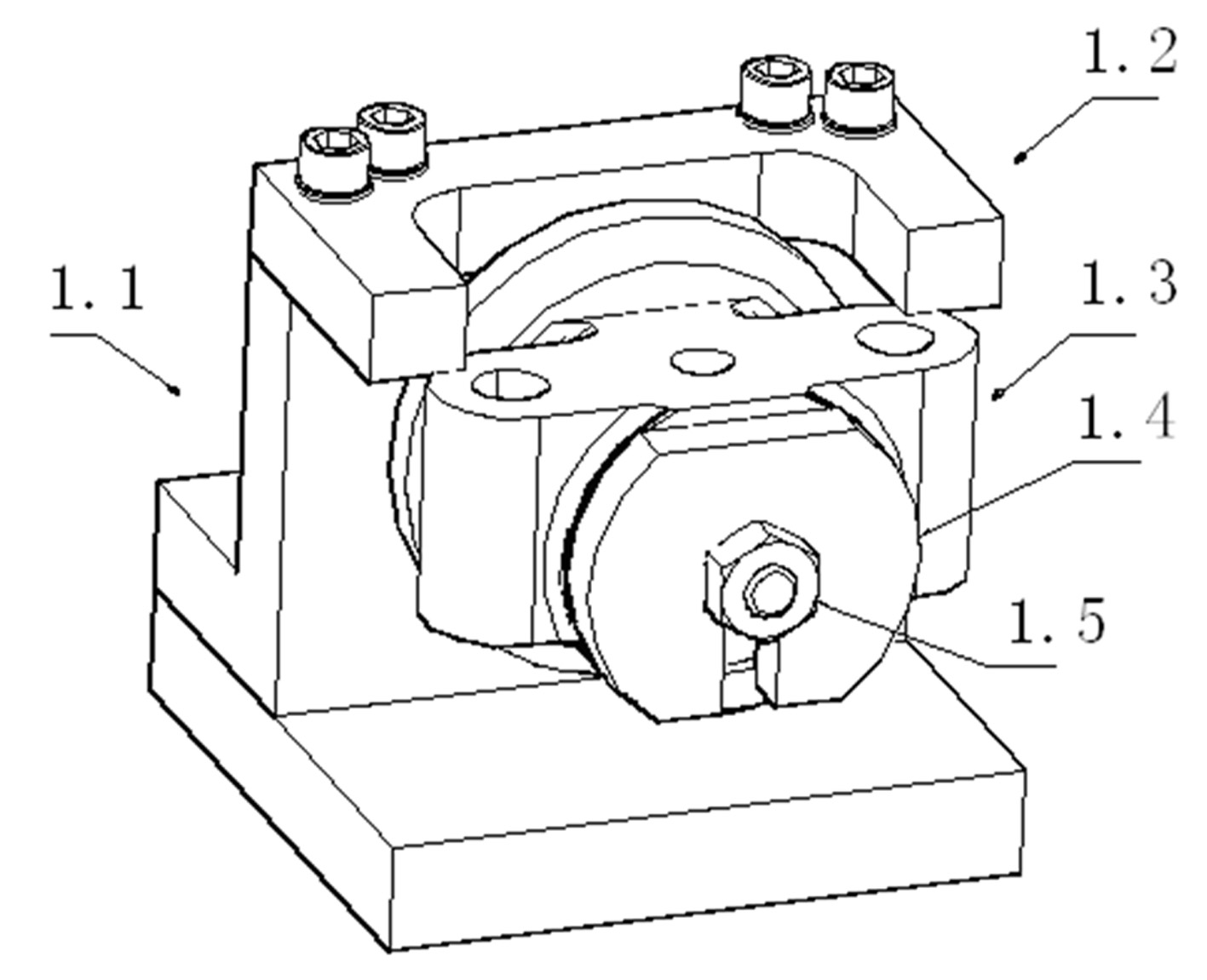
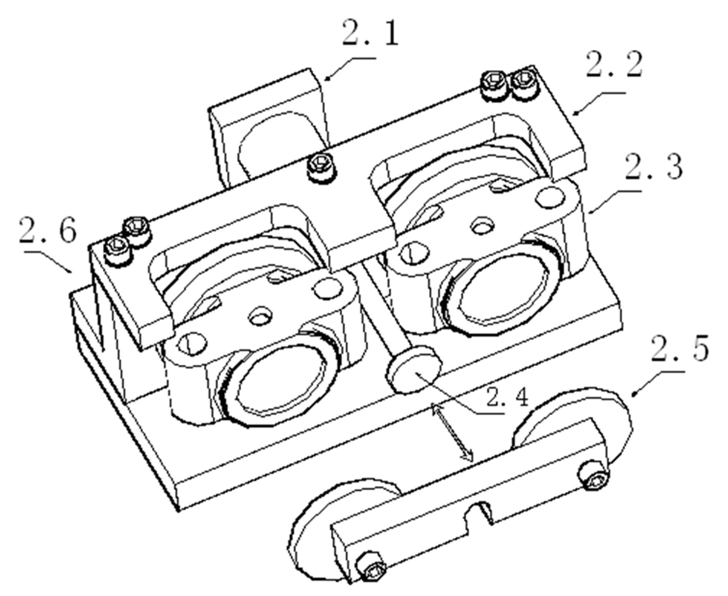
[0012] A shaft cover processing tool, including an angle iron mandrel positioning seat 2.6, a positioning plate 2.2 and a pressure plate 2.5, the positioning plate 2.2 is connected to the angle iron mandrel positioning seat 2.6 to form a space for limiting the shaft cover 2.3. It also includes a cylinder 2.1; the angle iron mandrel positioning seat 2.6 has the same two groups, and the two sets of angle iron mandrel positioning seats 2.6 are arranged side by side; a cylinder pull rod 2.4 is arranged in the middle of the two sets of angle iron mandrel positioning seats 2.6, The cylinder rod 2.4 is connected to the piston rod of the cylinder 2.1, and advances and retreats synchronously with the piston rod; the axial direction of the cylinder rod 2.4 is parallel to the axial direction of the mandrel on the angle iron mandrel positioning seat 2.6; the cyli...


PUM


Abstract

The invention discloses a shaft cover processing tool, which comprises angle iron core rod positioning seats, positioning plates and pressing plates, wherein the positioning plates are connected with the angle iron core rod positioning seats to form shaft cover limit. The tool also comprises a cylinder; two groups of angle iron core rod positioning seats are the same and arranged side by side; a cylinder pull rod is arranged between the two groups of angle iron core rod positioning seats, and the cylinder pull rod is connected on a piston rod of the cylinder and synchronously advances and retreats with the piston rod; the axial direction of the cylinder pull rod is parallel to the axial directions of core rods on the angle iron core rod positioning seats, and the front end of the cylinder pull rod is provided with a baffle plate; the number of the pressing plates is two, and the two pressing plates are interconnected; and the baffle plate is detachably connected with the two pressing plates, namely when the baffle plate and the two pressing plates are in an assembly state, the two pressing plates act under the traction of the cylinder pull rod. After the technical scheme is adopted, two workpieces can be assembled at the same time, the dwell time of a processing center due to assembly and disassembly of the workpieces is saved, the processing center obtains highest utilization rate, and the batch yield is improved.

Description

technical field [0001] The invention belongs to the technical field of mechanical processing, in particular to a shaft cover processing tool. Background technique [0002] Three holes need to be processed on the shaft cover. In the prior art, such as figure 1 The machining tool shown clamps the workpiece and then drills the hole in the workpiece. The workpiece 1.3 is positioned with the angle iron mandrel positioning seat 1.1 and the positioning plate 1.2, and then pressed with the pressure plate 1.4 and the locking nut 1.5. After the drilling is completed, stop the machine to change the workpiece, and then start the machine after clamping. There is a mandrel in the angle iron mandrel positioning seat, the shaft cover is sleeved on the mandrel, and the position is limited by the positioning plate installed on the angle iron mandrel positioning seat; then the pressure plate is set on the mandrel, and finally Tighten with bolts. [0003] With this kind of tooling, it is ne...

Claims


Application Information

Patent Timeline
Patent Type & Authority Applications(China)
IPC IPC(8): B23Q3/06
Inventor 吕燕翔吕伟龙史仁龙万传友彭芳美周国忠
Owner 溧阳市虹翔机械制造有限公司
Why Eureka
Try Eureka