Bottle blank conveying chain of bottle blowing machine

A conveyor chain and bottle blowing machine technology, which is applied in the field of preform conveyor chain, can solve the problems of insufficient use of heat in the heating box, uneven rotation of the conveyor chain, and non-adjustable distance between preforms, etc., to achieve fewer parts, The effect of firmly supporting the preform tube and low replacement cost

Inactive Publication Date: 2011-02-02
北京华融塑胶有限公司
View PDF10 Cites 6 Cited by
  • Summary
  • Abstract
  • Description
  • Claims
  • Application Information

AI Technical Summary

Problems solved by technology

[0003] Since the existing preforms are placed adjacent to each other according to the diameter of the blown bottle body, the distance between the preforms is relatively large, and the length of the horizontal heating tube is fixed. In the heating stroke corresponding to the length of the heating tube, The number of heated preforms is small, the production efficiency is low, and the heat generated by the heating box cannot be fully utilized, resulting in serious waste of heat
On the other hand, the existing conveyor chain is installed with preform seats on the chain, the distance between the preforms is not adjustable, the structure is complex, the mass is large, the energy consumption is high, and the conveyor chain is prone to uneven rotation, resulting in uneven heating of the preforms. The blown bottle has uneven wall thickness

Method used


Image

  • Bottle blank conveying chain of bottle blowing machine
  • Bottle blank conveying chain of bottle blowing machine
  • Bottle blank conveying chain of bottle blowing machine

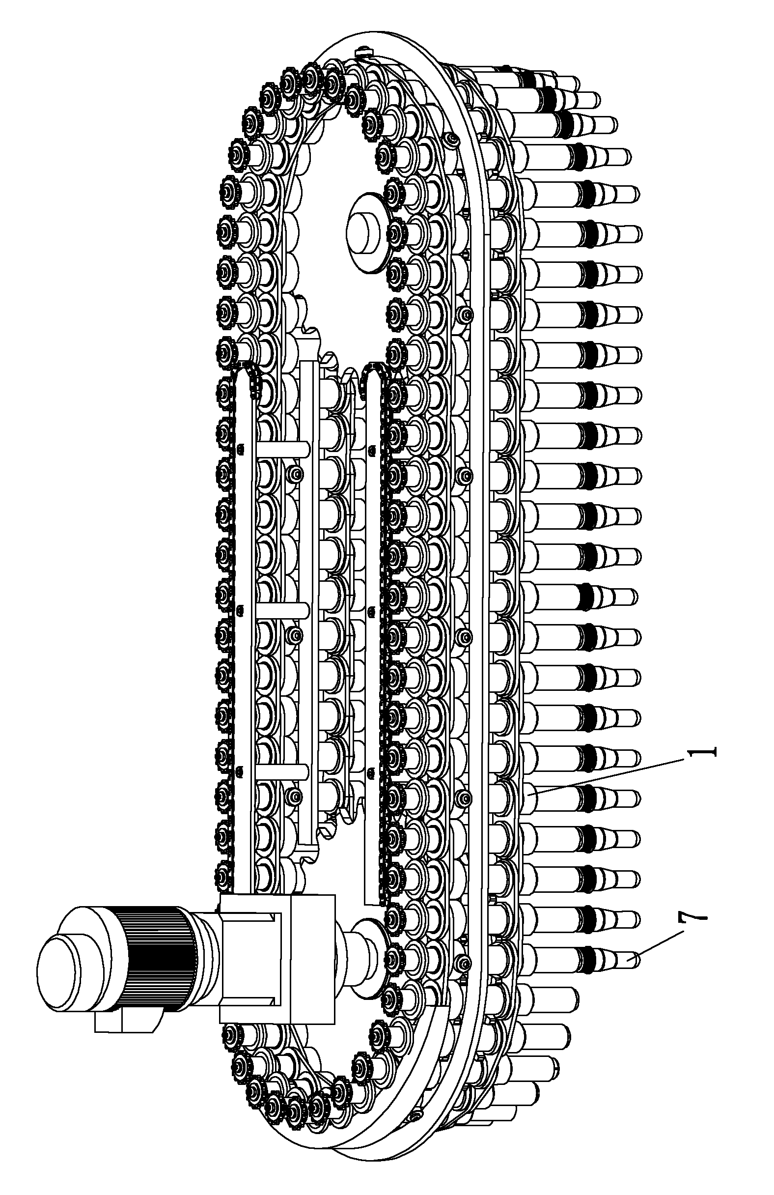
Examples


Embodiment Construction

[0023] The present invention will be further described below through embodiments in conjunction with the accompanying drawings.

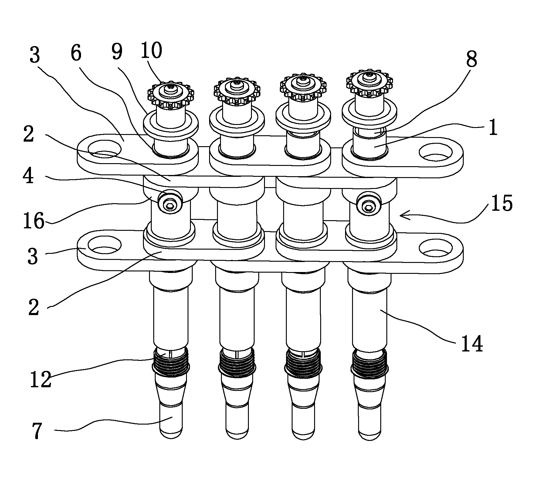
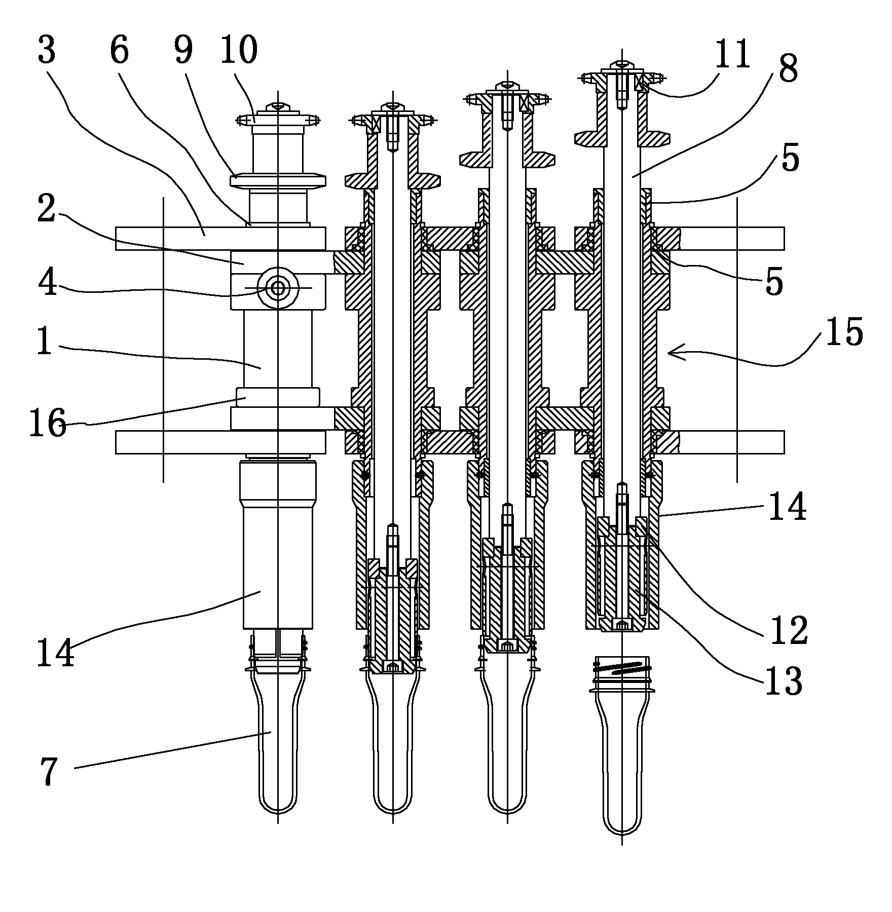
[0024] like Figure 1-Figure 5 As shown, the preform conveying chain of a bottle blowing machine described in this embodiment includes a preform seat 1 which is a hollow tubular part, and each preform seat 1 is connected to the left, The adjacent preform bases 1 on the right are connected to form an annular chain. The preform bases 1 are erected and pass through the flat inner and outer chain plates. The inner chain piece 2 and the outer chain piece 3 are superimposed. superimposed. The inner chain piece 2 can be fixed on the preform holder 1 with screws. A shaft sleeve 5 is installed between the outer chain piece 3 and the preform seat 1 and can rotate relatively. Each preform seat 1 is provided with two annular protrusions 16 at the position between the two inner chain pieces 2 , and a driving tooth slot 15 is formed between the two annular pro...


PUM


Abstract

The invention discloses a bottle blank conveying chain of a bottle blowing machine, relates to the bottle blowing machine, and solves the technical problem of large space of bottle blanks conveyed by the conveying chain of the conventional bottle blowing machine. The bottle blank conveying chain comprises bottle blank seats. The bottle blank conveying chain is characterized in that: the bottle blank seats are tubular pieces, each bottle blank seat is connected with the left and right adjacent bottle blank seats through an inner chain sheet and an outer chain sheet in up-and-down symmetry to form an annular chain respectively, the inner chain sheet and the outer chain sheet are placed horizontally and penetrated by the vertical bottle blanks, and the inner chain sheet and the outer chain sheet are superposed at the superposition part. The bottle blank seats are arranged at the positions of chain link connecting pins of the traditional chain so as to fix the bottle blanks, connect the chain sheets, optimize the structure of the conveying chain and reduce the mass of the conveying chain along with low running energy consumption; and the space of the bottle blanks can be reduced as much as possible by adopting the inner and outer chain sheets with adjacent center distance so that the radiation heat can be fully utilized.

Description

technical field [0001] The invention relates to the technical field of bottle blowing machines, in particular to a bottle blank conveying chain of the bottle blowing machine. Background technique [0002] The bottle blowing machine is a kind of preform that heats the injection-molded preform tube (referred to as "preform"), then puts the preform heated to the set temperature into the mold, and then blows the preform into a bottle with pressurized air. equipment. The heating condition of the preform plays a key role in the quality of the blown bottle and the energy consumption of the blow molding machine. When the plastic preforms are fed into the blow molding machine by the automatic feeding machine, the conveying mechanism in the blow molding machine sends the preforms into the heating box at a constant speed, so that they are heated to a temperature suitable for blowing into the bottle body. When the preform passes through the heating box, in addition to revolving with t...

Claims


Application Information

Patent Timeline
Patent Type & Authority Applications(China)
IPC IPC(8): B29C31/08B29C49/42
Inventor 张士生
Owner 北京华融塑胶有限公司
Why Eureka
Try Eureka