
Ignitor discharge time extending device

A technology of discharge time and extension device, applied in the direction of capacitor energy storage device, etc., can solve the problems of short ignition time of spark plug, difficult ignition of gasoline, difficult start, etc. Effect

Inactive Publication Date: 2011-11-30
如皋市丁堰镇工业园区开发有限公司
View PDF6 Cites 0 Cited by
  • Summary
  • Abstract
  • Description
  • Claims
  • Application Information

AI Technical Summary

Problems solved by technology

Although the current DC igniter (DC-CDI) has overcome the low charging efficiency of the early AC igniter (AC-CDI), the transformer in the DC-CDI has completely overcome the function that the capacitor charging cannot be fully saturated, but the discharge speed of the capacitor Fast, short time, resulting in a short ignition time of the high pressure package to the spark plug, and gasoline is not easy to ignite, especially in winter, when the temperature is low, the spark on the spark plug lasts for a short time, which makes it difficult to start and consumes a lot of fuel

Method used


Image

  • Ignitor discharge time extending device
  • Ignitor discharge time extending device

Examples


Embodiment Construction

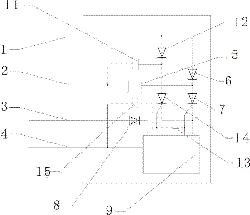
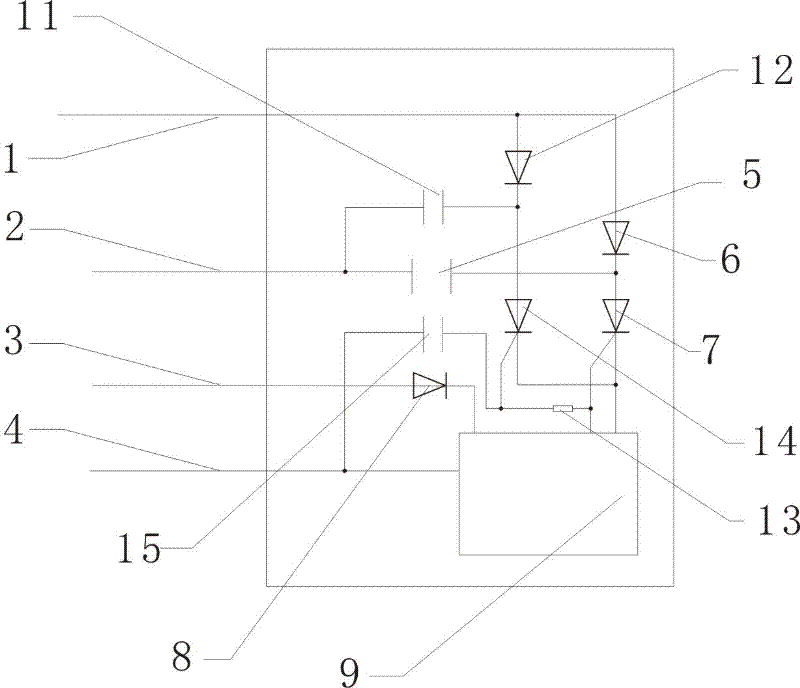
[0008] Accompanying drawing is the structural diagram of a kind of igniter discharge time prolonging device of the present invention in DC igniter, and its structure is by the first capacitor 11 and the first diode 12, resistance 13, the first thyristor 14, the second capacitor 15. In the drawings, the discharge end of the first capacitor 11 is connected to the discharge end of the third capacitor 5, the other end is connected to the first diode 12, the first thyristor 14 is connected to the first diode 12, and the second One end of the capacitor 15 is connected to the fourth line 4 , the other end is connected to the resistor 13 , and the other end of the resistor 13 is connected to the trigger end of the second thyristor 7 . In the drawings, except the first capacitor 11, the first diode 12, the resistor 13, the first thyristor 14, and the second capacitor 15 are added delay discharge control circuits, the rest are standard configurations of the original igniter itself.

[...


PUM


Abstract

The present invention relates to an ignitor discharge time extending device which comprises a first capacitor, a second diode, a resistor, first controlled silicon and a second capacitor. The ignitor discharge time extending device is characterized in that the discharge end of the first capacitor is connected with the discharge end of a third capacitor, the other end of the first capacitor is connected with the first diode, the first controlled silicon is connected with the first diode, one end of the second capacitor is connected with a fourth line and the other end thereof is connected with the resistor, and the other end of the resistor is connected with the trigger end of the second controlled silicon. The ignitor discharge time extending device provided by the present invention has the advantages of remarkably improving the continuous discharge time of a spark plug, ensuring that a vehicle is well started and the acceleration is more stable, reducing the oil consumption and decreasing the tail gas emission.

Description

technical field [0001] The invention relates to a discharge control device of a motorcycle igniter, in particular to a device for extending the discharge time of the igniter. Background technique [0002] The discharge control of the motorcycle CDI igniter adopts a capacitor discharge structure. The charging is rectified by a diode and then charged to the capacitor. The trigger signal is rectified and filtered and then sent to the controller. Silicon, SCR conduction capacitor discharges, forming a duty cycle. Although the current DC igniter (DC-CDI) has overcome the low charging efficiency of the early AC igniter (AC-CDI), the transformer in the DC-CDI has completely overcome the function that the capacitor charging cannot be fully saturated, but the discharge speed of the capacitor Fast, short time, resulting in a short ignition time of the high-voltage package to the spark plug, gasoline is not easy to ignite, especially in winter, when the temperature is low, the spark ...

Claims


Application Information

Patent Timeline
Patent Type & Authority Patents(China)
IPC IPC(8): F02P3/08
Inventor 庄景阳
Owner 如皋市丁堰镇工业园区开发有限公司
Learn More