
Substrate processing equipment and ejector pin lifting device

A technology of substrate processing equipment and lifting devices, applied in the direction of transportation and packaging, conveyor objects, electrical components, etc., can solve problems such as crystal slipping, small adjustment range, and complicated leveling, and reduce the possibility of positional deviation , Improve safety and reliability, good shock absorption effect

Active Publication Date: 2012-09-05
BEIJING NAURA MICROELECTRONICS EQUIP CO LTD
View PDF3 Cites 0 Cited by
  • Summary
  • Abstract
  • Description
  • Claims
  • Application Information

AI Technical Summary

Problems solved by technology

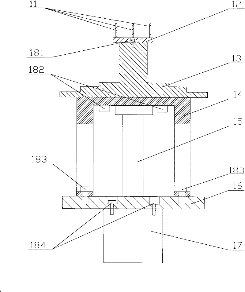
[0006] When the crystal to be processed is placed on the top of the thimble 11 and the thimble 11 lifts the wafer, there is a certain relative speed between the wafer and the thimble 11, and the two will collide. Rigid connection, and the weight of the chip itself is relatively light, so when it collides with the thimble, the chip will bounce upward due to the kinetic energy contained therein, which will easily cause the crystal to slide off the thimble 11, causing the thimble to rise and fall Lower safety and reliability of the device
[0007] At the same time, when the level of the plane formed by the top of the thimble and the plane of the incoming crystal is quite different, the phenomenon of crystal slipping is also prone to occur. Therefore, it is necessary to adjust the level of the plane on which the top surface of the thimble is located, so as to satisfy the gap between the two. The relative level between; the above prior art adjusts the level of the device by adjusting the first adjusting screw 183 and the second adjusting screw 184, which is not only complicated in leveling, but also has a small adjustment range
[0008] In addition, the high consumption part of the thimble lifting device is the thimble 11, and the fixing seat 12 supporting the thimble 11 is generally not damaged. In the above-mentioned prior art, the thimble 11 and the fixing seat 12 are fixedly connected. When damaged, it can only be replaced as a whole, resulting in a waste of material for the fixing seat 12

Method used


Image

  • Substrate processing equipment and ejector pin lifting device
  • Substrate processing equipment and ejector pin lifting device
  • Substrate processing equipment and ejector pin lifting device

Examples


Embodiment Construction

[0028] The core of the present invention is to provide a thimble lifting device for substrate processing equipment, which can effectively prevent the crystal from slipping off the thimble when it is in contact with the thimble, thus having high safety and reliability. Another core of the present invention is to provide a substrate processing equipment including the above ejector pin lifting device.

[0029] In order to enable those skilled in the art to better understand the solution of the present invention, the present invention will be further described in detail below in conjunction with the accompanying drawings and specific embodiments.

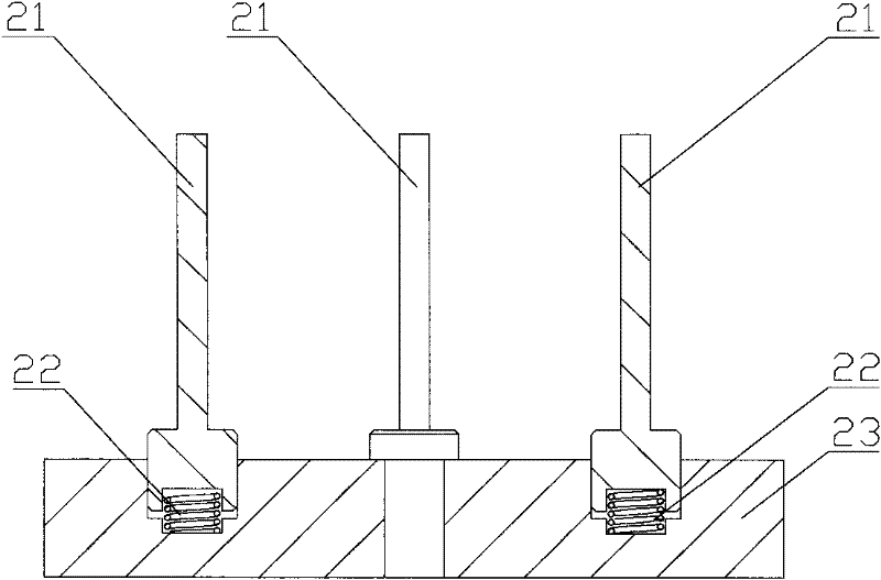
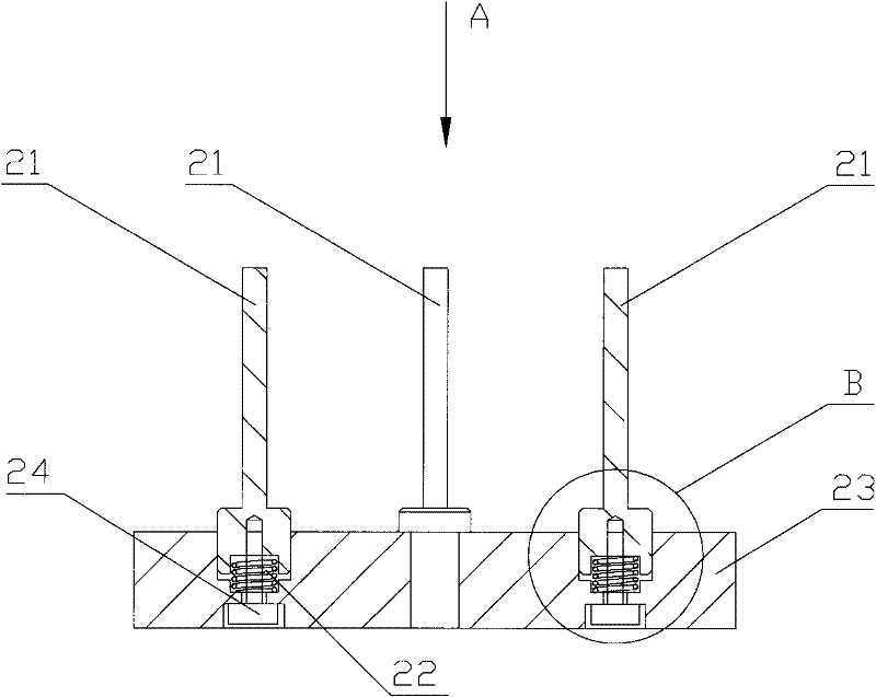
[0030] Please refer to figure 2 , figure 2 It is a structural schematic diagram of a specific embodiment of the thimble lifting device provided by the present invention.

[0031] In a specific embodiment, the thimble lifting device provided by the present invention includes a cylinder located at the lower part of the device, the cyl...


PUM


Abstract

The invention discloses an ejector pin lifting device for substrate processing equipment, which comprises a permanent seat and at least three ejector pins supported on the upper surface of the permanent seat, wherein the ejector pins and the permanent seat can relatively move in a vertical direction, and a damping part is arranged between the ejector pins and the permanent seat. Thus, when a processed crystal is transferred in and out of a reaction chamber and collides with the ejector pins, the damping part converts the kinetic energy of a motion part into the energy of other forms so as to achieve a better damping effect, effectively reduce the probability of position shift of the processed crystal and prevent the processed crystal falling from the ejector pins, so that the safety and reliability of the device are further improved. The invention also discloses the substrate processing equipment comprising the ejector pin lifting device.

Description

technical field [0001] The invention relates to the field of semiconductor processing, in particular to an ejector pin lifting device for substrate processing equipment. The present invention also relates to a substrate processing equipment comprising the above ejector pin lifting device. Background technique [0002] With the rapid development of my country's economic construction, the market demand for semiconductor components is increasing, which has led to the rapid development of the semiconductor processing industry. [0003] At present, the interior of the process chamber for processing semiconductor substrates generally has an electrostatic chuck, which is used to support semiconductor substrates such as crystals to be processed, and its lower part is provided with a lifting device. The thimbles supporting the processed crystal, the number of thimbles is generally four. When processing crystals, the transfer platform transfers the crystals into the process chamber,...

Claims


Application Information

Patent Timeline
Patent Type & Authority Patents(China)
IPC IPC(8): H01L21/683H01L21/677H01L21/00
Inventor 管长乐
Owner BEIJING NAURA MICROELECTRONICS EQUIP CO LTD
Learn More