
Electron accelerator

A technology of accelerators and high-voltage electrodes, used in DC voltage accelerators, electrical components, accelerators, etc.

Active Publication Date: 2010-12-08
CGN ACCELERATOR TECH SUZHOU CO LTD
View PDF0 Cites 0 Cited by
  • Summary
  • Abstract
  • Description
  • Claims
  • Application Information

AI Technical Summary

Problems solved by technology

The pressure equalizing ring with such a hollow tube structure increases the weight of the pressure equalizing ring due to the arrangement of the inner side of the circular arc which has no effect. Moreover, the stainless steel material used in the existing pressure equalizing ring has a relatively high density because of its high density. The weight of the pressure equalizing ring has been greatly increased, and the pressure equalizing ring needs to be installed on the stem during the working process. The heavy weight will affect the installation stability of the pressure equalizing ring, and then affect the work of the accelerator.
[0005]The pressure equalizing ring of this structure can only be processed by mechanical pressing or sheet metal working by bending pipes into a ring, and it cannot be processed at one time Molding, mass production, not only the processing process is complicated, but more importantly, it is difficult to ensure that each equalizing ring has the same physical characteristics, and the scrap rate is high
During use, due to the high voltage between the grading ring and the high-frequency electrode, the inconsistency between the grading rings will cause electric field distortion, affect the high-voltage resistance level and high-voltage stability of the accelerator, and cause corona and breakdown and other phenomena, and make the insulation characteristics between the grading ring and the high-frequency electrode worse

Method used


Image

  • Electron accelerator
  • Electron accelerator
  • Electron accelerator

Examples


Embodiment Construction

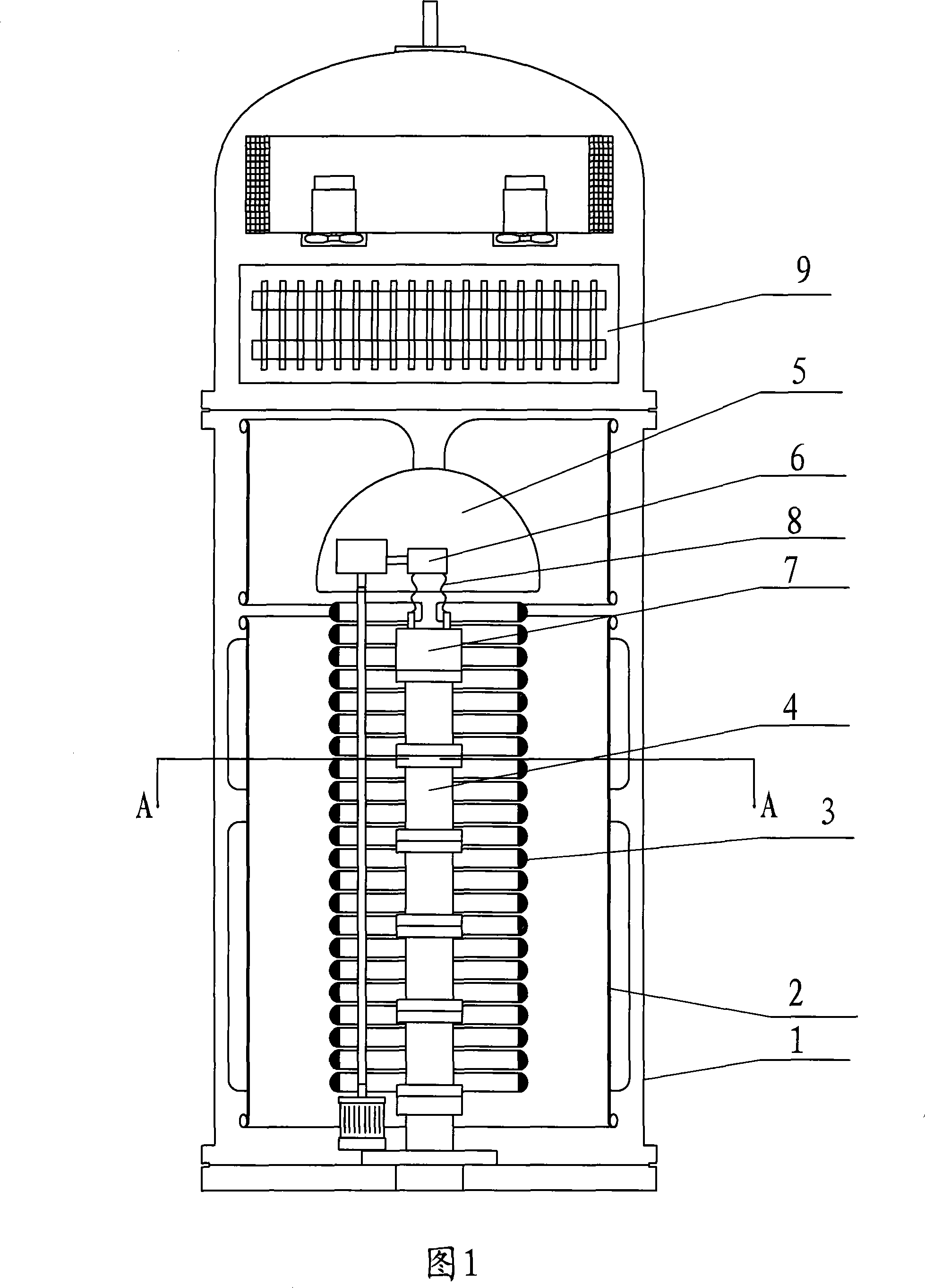
[0019] Such as figure 1 The shown accelerator includes a steel cylinder 1, a high-frequency transformer 9 arranged above the steel cylinder 1, a plurality of semicircular equalizing rings 3 arranged inside the steel cylinder 1, and a high-voltage electrode 5 arranged above the equalizing ring 3 , two high-frequency electrodes 2 arranged on the outside of the equalizing ring 3 and the high-voltage electrode 5, an electron gun 7 with a filament 8 for generating and exciting electrons, a filament transformer 6 for adjusting the voltage of the filament 8, and an electron gun 7 arranged on the Accelerator tube 4 below the vacuum.

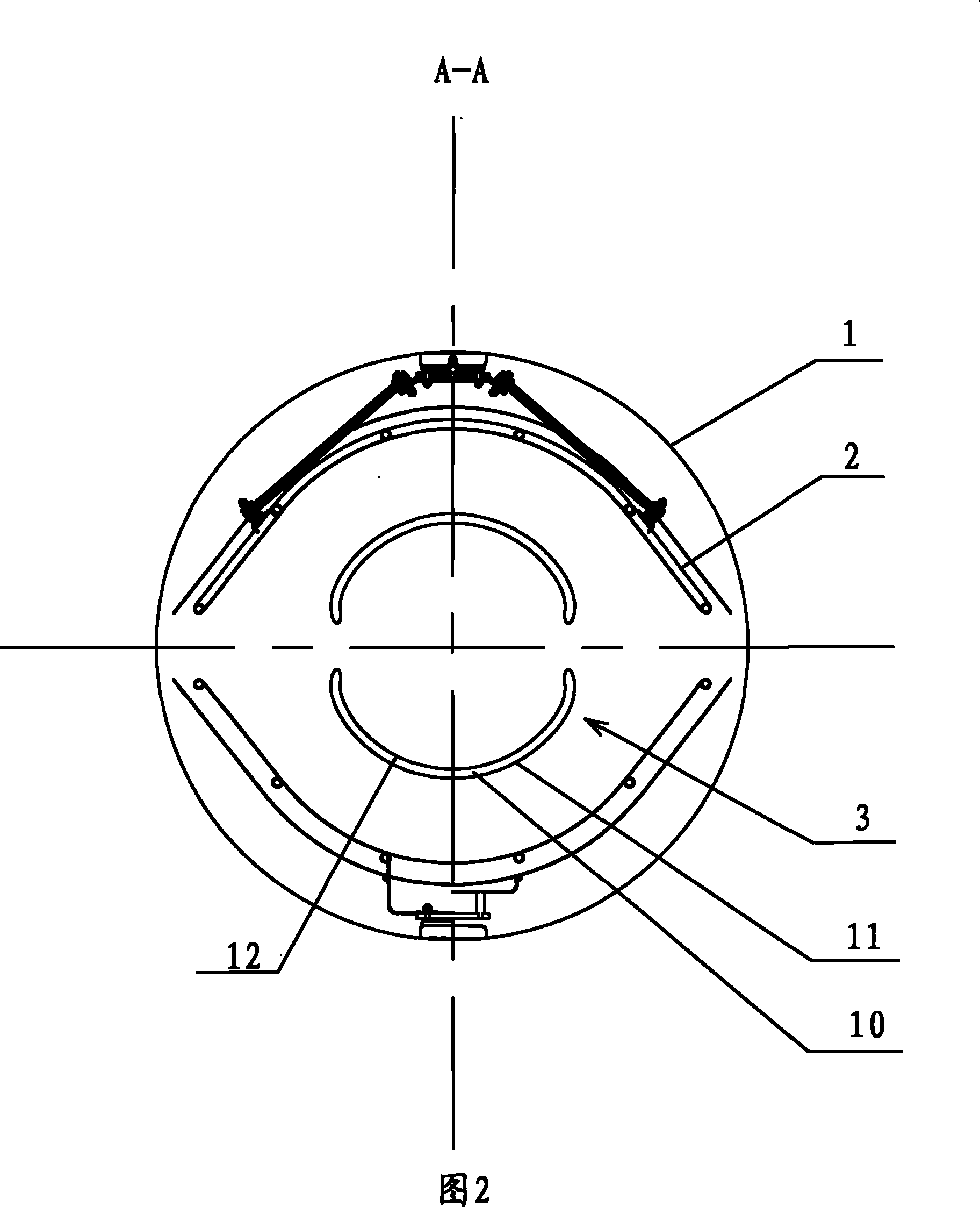
[0020] A plurality of semicircular pressure equalizing rings 3 are symmetrically arranged in two rows along the axis of the steel cylinder 1 with their openings facing each other. Such as figure 2 As shown, the equalizing ring 3 is arranged inside the high-frequency electrode 2 , and the steel drum 1 of the accelerator is surrounded outside the high-...


PUM


Abstract

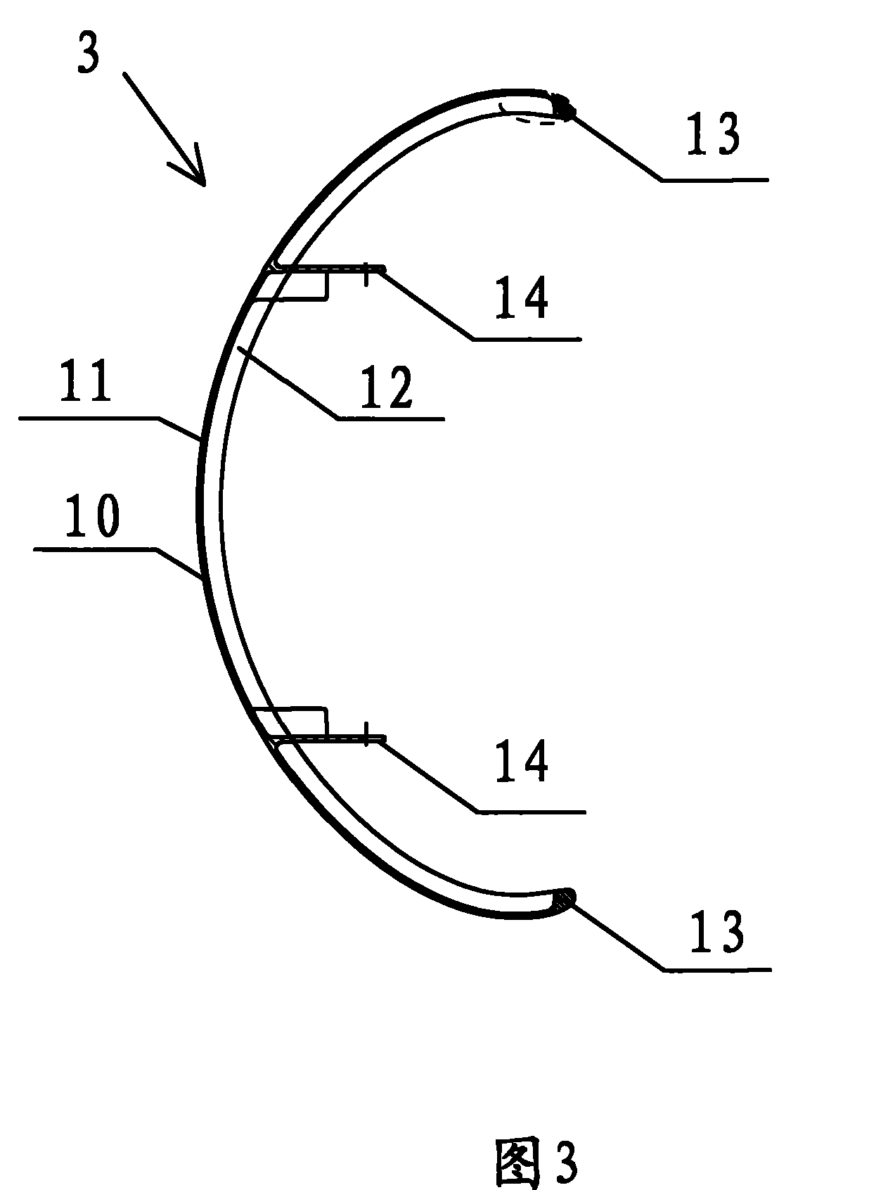
An accelerator comprises a steel cylinder, a high-frequency transformer which is arranged on the steel cylinder, a plurality of semi-circular equalizer rings which are arranged inside the steel cylinder, a high pressure electrode which is arranged on the equalizer rings, two pieces of high-frequency electrodes which are arranged outside the equalizer rings and the high pressure electrode, an electron gun which is used to produce and excite electrons with a filament, a filament transformer which is used to regulate filament voltage and a vacuum accelerating tube which is arranged under the electron gun, wherein a plurality of semi-circular equalizer rings adopt a mode that openings are opposite to symmetrically line up into two lines along the steel cylinder axial cord direction. The equalizer rings comprise ring bodies, connecting pieces which are fixedly connected with the ring bodies and two end portions which are located on two ends of the ring bodies, wherein the whole equalizer rings are provided with C-shaped cross sections, the ring bodies are provided with outer surfaces which are corresponded with the steel cylinder and inner surfaces which are corresponded with the outersurfaces, the indent sides of C-shaped cross sections openings are inner surfaces, and the inner surfaces are arranged to the axial cord of the steel cylinder. The accelerator has the characteristicsof simple structure, light weight, good ring gap consistency.

Description

Technical field [0001] The present invention involves an accelerator, especially an electronic accelerator. Background technique [0002] In existing technologies, the accelerator used to accelerates the following components is composed of the following components: the cold trap settled on the top of the steel tube, the high -frequency transformer set at the top of the steel tube, the high -voltage electrode setting under the high -frequency transformer, setting the settings, settingThe core columns inside the steel tube and below the high -voltage electrode, and the two rows of the two rows (also known as the electric halo ring) on the core column in the center line of the steel tube are arranged.2. High -frequency transformer connect and set up two high -frequency electrodes on the outside of the two rows, electronic guns used to stimulate electrons, vacuum acceleration pipes located under the electronic gun, power supply device for electronic guns for electronic guns, for adju...

Claims


Application Information

Patent Timeline
Patent Type & Authority Patents(China)
IPC IPC(8): H05H5/00H05H5/02
Inventor 俞章华叶启捷
Owner CGN ACCELERATOR TECH SUZHOU CO LTD
Learn More