
Method for converting boundary element by extra-high voltage direct current transmission line mode voltage S

An ultra-high voltage DC and DC voltage technology, applied in the direction of DC network circuit devices, electrical components, circuit devices, etc., can solve the problem of DC protection device refusal to operate, directional traveling wave change rate affected by transition resistance, voltage change rate reduction, etc. question

Active Publication Date: 2011-02-02
KUNMING UNIV OF SCI & TECH
View PDF1 Cites 21 Cited by
  • Summary
  • Abstract
  • Description
  • Claims
  • Application Information

AI Technical Summary

Problems solved by technology

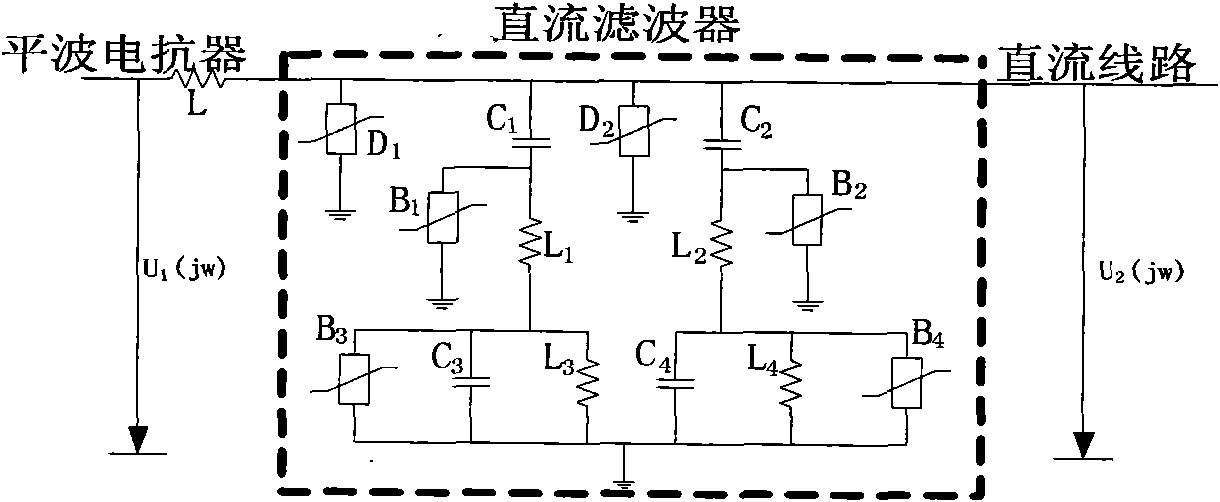
However, according to the relevant data of actual operation at home and abroad, the currently used DC line traveling wave protection (mainly provided by ABB and SIEMENS) is affected by the presence of smoothing reactors and DC filters at the end of the line, resulting in voltage changes rate reduction; voltage variables and ground mode waves are affected by fault distance; directional traveling wave change rate is affected by transition resistance, etc.
It is precisely because of the existence of these influencing factors that sometimes the existing DC protection device will refuse to operate.

Method used


Image

  • Method for converting boundary element by extra-high voltage direct current transmission line mode voltage S
  • Method for converting boundary element by extra-high voltage direct current transmission line mode voltage S
  • Method for converting boundary element by extra-high voltage direct current transmission line mode voltage S

Examples


Embodiment Construction

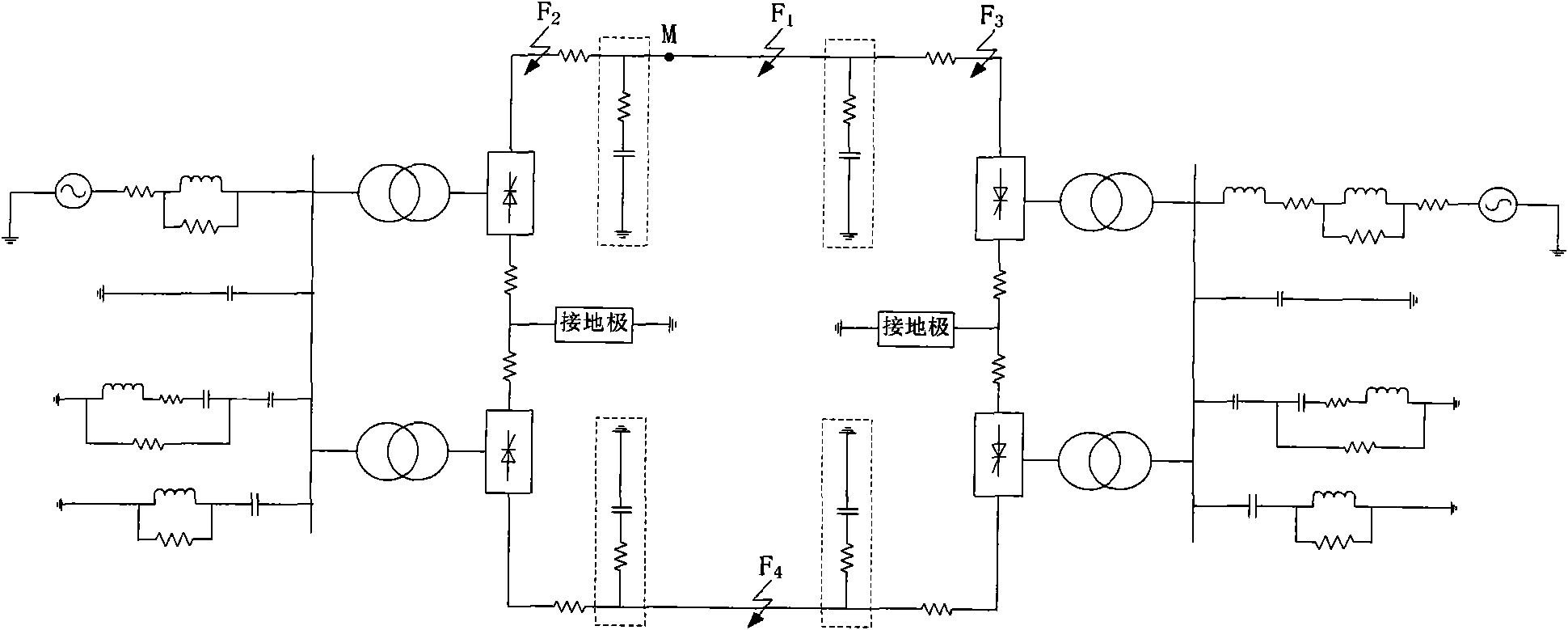
[0075] Simulation model such as figure 1 As shown, a positive ground fault occurs 150km away from the protection installation, the time window length is 2ms, and the sampling frequency is 100kHz.

[0076] (1) After the DC line fails, the starting element starts immediately, according to the formula:

[0077] u 1 =(u + -u - ) (1)

[0078] Find the line-mode voltage u 1 , the line-mode voltage waveform is as Figure 5 as shown in (a);

[0079] (2) According to the formula

[0080] S [ m , n ] = Σ k = 0 N - 1 U [ n + k ] e - 2 π 2 k 2 / ...


PUM


Abstract

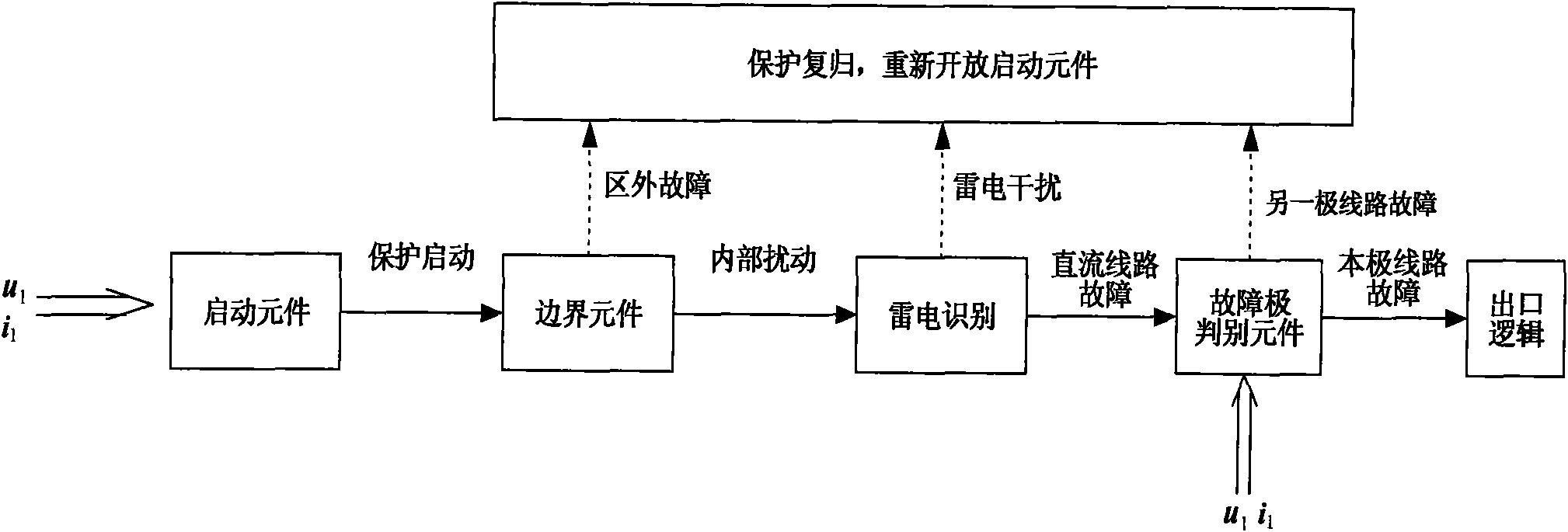
The invention discloses a method for converting a boundary element by an extra-high voltage direct current transmission line mode voltage S, comprising the following steps: when the direct current line is in fault, after a protective element is started, the line mode voltage is obtained by utilizing a phase mode transformational theory according to the two-pole direct current voltage detected on a protection installation part; a dispersion line mode voltage signal is selected to perform S conversion, wherein the sample sequence length is 200 points, and the conversion result is 101*200 time frequency complex matrix; mode calculation is performed on each element in the complex matrix; the high-frequency energy and the low-frequency energy of the line mode voltage are extracted according tothe obtained mode matrix; the ratio of the high-frequency energy and the low-frequency energy of the line mode voltage is calculated; the faults in the cell and out of the cell are distinguished according to the ratio of the high-frequency energy and the low-frequency energy. A large amount of stimulated results prove that the method of the invention has better effect.

Description

technical field [0001] The invention relates to the technical field of electric power system relay protection, in particular to a fault boundary element method of UHV direct current transmission line using line model voltage S to transform energy ratio. Background technique [0002] At present, how to improve the safety and reliability of DC line operation has become an urgent problem to be solved. Whether the DC line fault can be correctly judged is the key to DC line protection. At present, traveling wave protection is widely used in the world as the main protection of high-voltage DC line protection. Its fast single-ended protection is based on the sudden change of voltage traveling wave, the rate of change of voltage traveling wave and the gradient of current change as criteria. It has ultra-high-speed action characteristics, and is not affected by current transformer saturation, system oscillation and long-term distributed capacitance. However, according to the relevan...

Claims


Application Information

Patent Timeline
IPC IPC(8): H02H7/26H02J1/00
Inventor 束洪春田鑫萃张广斌孙士云张兰兰
Owner KUNMING UNIV OF SCI & TECH
Learn More