Automatic gain control method and control circuit suitable for orthogonal frequency division multiplexing (OFM) system

A technology of automatic gain control and gain adjustment circuit, which is applied in the field of communication and can solve the problems of long convergence time and the like

Inactive Publication Date: 2011-02-02
江西开昂教育股份有限公司
View PDF3 Cites 30 Cited by
  • Summary
  • Abstract
  • Description
  • Claims
  • Application Information

AI Technical Summary

Problems solved by technology

Generally, when each frame adjustment is used, when the signal variation range is too large, it

Method used


Image

  • Automatic gain control method and control circuit suitable for orthogonal frequency division multiplexing (OFM) system
  • Automatic gain control method and control circuit suitable for orthogonal frequency division multiplexing (OFM) system
  • Automatic gain control method and control circuit suitable for orthogonal frequency division multiplexing (OFM) system

Examples


Embodiment Construction

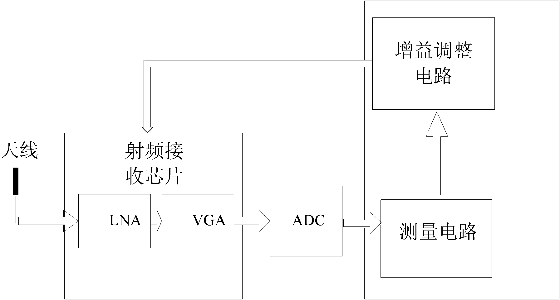
[0086] The automatic gain control circuit (AGC) mainly includes two parts: a signal energy measurement circuit and a gain adjustment circuit. The measurement circuit sums and averages the energy of the I-channel and Q-channel signals of the data sampled by the ADC in a sliding window, and selects the maximum value of the average energy of the sliding window in one frame and sends it to the gain adjustment circuit. The gain adjustment circuit selects the next appropriate gain configuration according to the energy measurement result of the energy measurement circuit and feeds it back to the low noise amplifier (LNA) and variable gain amplifier (VGA) of the front-end radio frequency receiving chip.

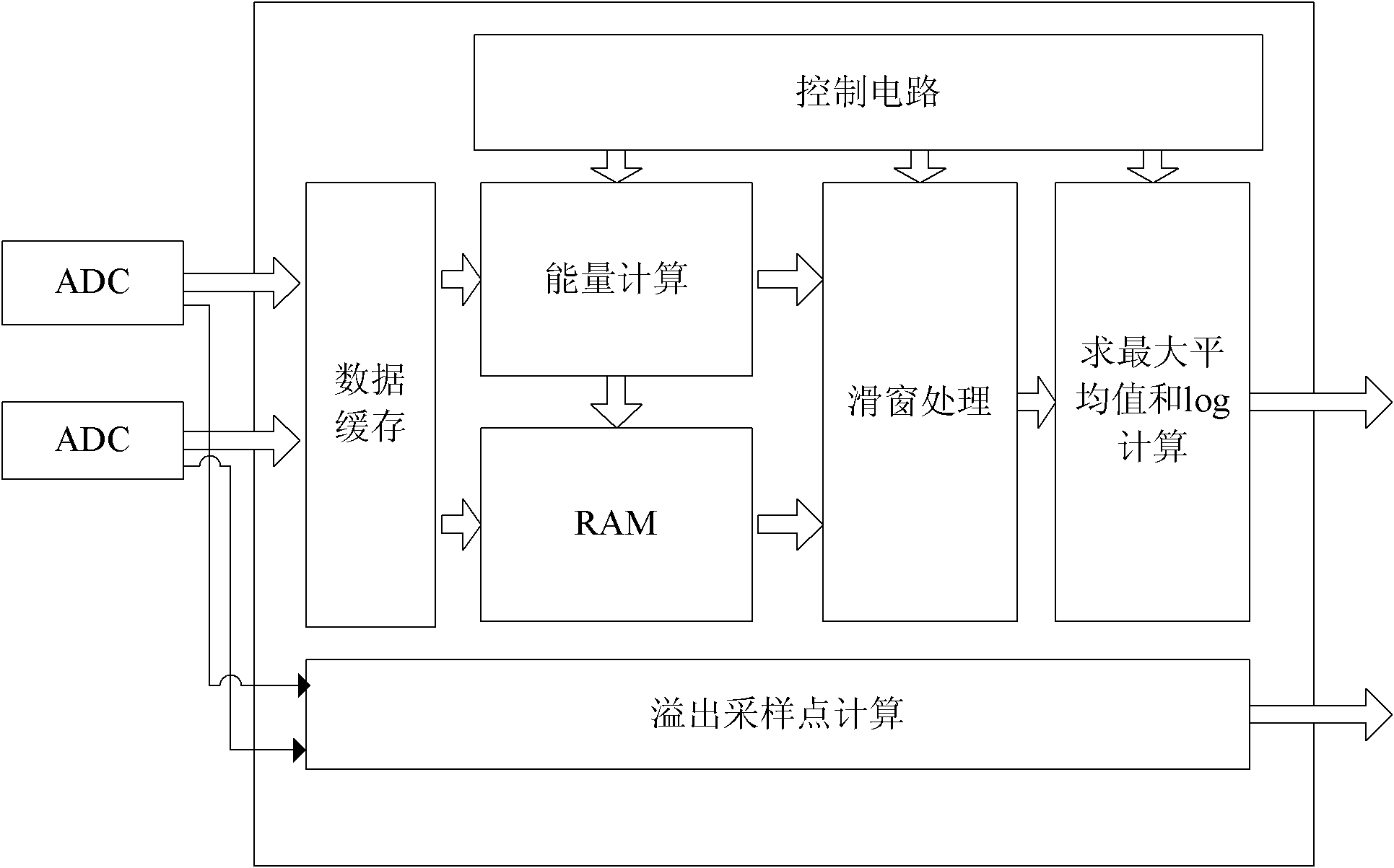
[0087] As wrong! Reference source not found. Shown is the structural diagram of the measurement circuit, which includes the control circuit, data buffer module, energy calculation module, sliding window processing module, energy storage module, maximum average value module, logarith...


PUM


Abstract

The invention discloses an automatic gain control method and an automatic gain control circuit which are suitable for an orthogonal frequency division multiplexing (OFM) system. The method comprises the following steps of: measuring a baseband signal; and adjusting gain. Slide window processing is performed during signal measuring so as to average signal energy in a window. A gain adjustment algorithm determines reasonable gain of the next adjustment period through conditions such as the gain of an upper frame, a measured value of the upper frame, the number of overflow sampling points, the receiving signal intensity indication on the current antenna and the like. Simultaneously, the gain of a radio frequency receiving chip is changed by circulating prefix time so as to track an OFDM symbol level.

Description

technical field [0001] The invention belongs to the technical field of communication, and in particular relates to an automatic gain control (AGC) realization method and circuit suitable for a wireless receiver. Background technique [0002] The automatic gain controller is an important part of the wireless communication system. The gain of the wireless receiver can be dynamically adjusted to adapt to receiving wireless signals of different strengths. [0003] The radio frequency signal generated by the transmitter is transmitted to the receiver through a wireless channel. Due to the influence of path attenuation and shadowing (shadowing), the signal will vary in a large range. In order to keep the signal entering the analog-to-digital converter (ADC) within an acceptable range. The gain of the amplifier in the radio frequency needs to be set reasonably to ensure that the signal entering the ADC will not be saturated, and the quantization range of the ADC can also be fully...

Claims


Application Information

Patent Timeline
IPC IPC(8): H04L27/26H04W52/52
Inventor 韩彬李宏李仁男李永王明源
Owner 江西开昂教育股份有限公司
Why Eureka
Try Eureka