Power generation device with two mobile parts

A technology for generating equipment and actuating equipment, which is applied in the direction of electrical components, circuits, electromechanical devices, etc., can solve the problems of high cost and increased switch size, and achieve the effect of improving performance level and optimizing floor space

Inactive Publication Date: 2011-02-02
SCHNEIDER ELECTRIC IND SAS
View PDF3 Cites 4 Cited by
  • Summary
  • Abstract
  • Description
  • Claims
  • Application Information

AI Technical Summary

Problems solved by technology

In order to improve the performance level of the converter it is necessary, for example, to increase the number of turns of the coil, which increases the size of the switch and makes it much more expensive considering the cost of the copper wire used for the winding

Method used


Image

  • Power generation device with two mobile parts
  • Power generation device with two mobile parts
  • Power generation device with two mobile parts

Examples


Embodiment Construction

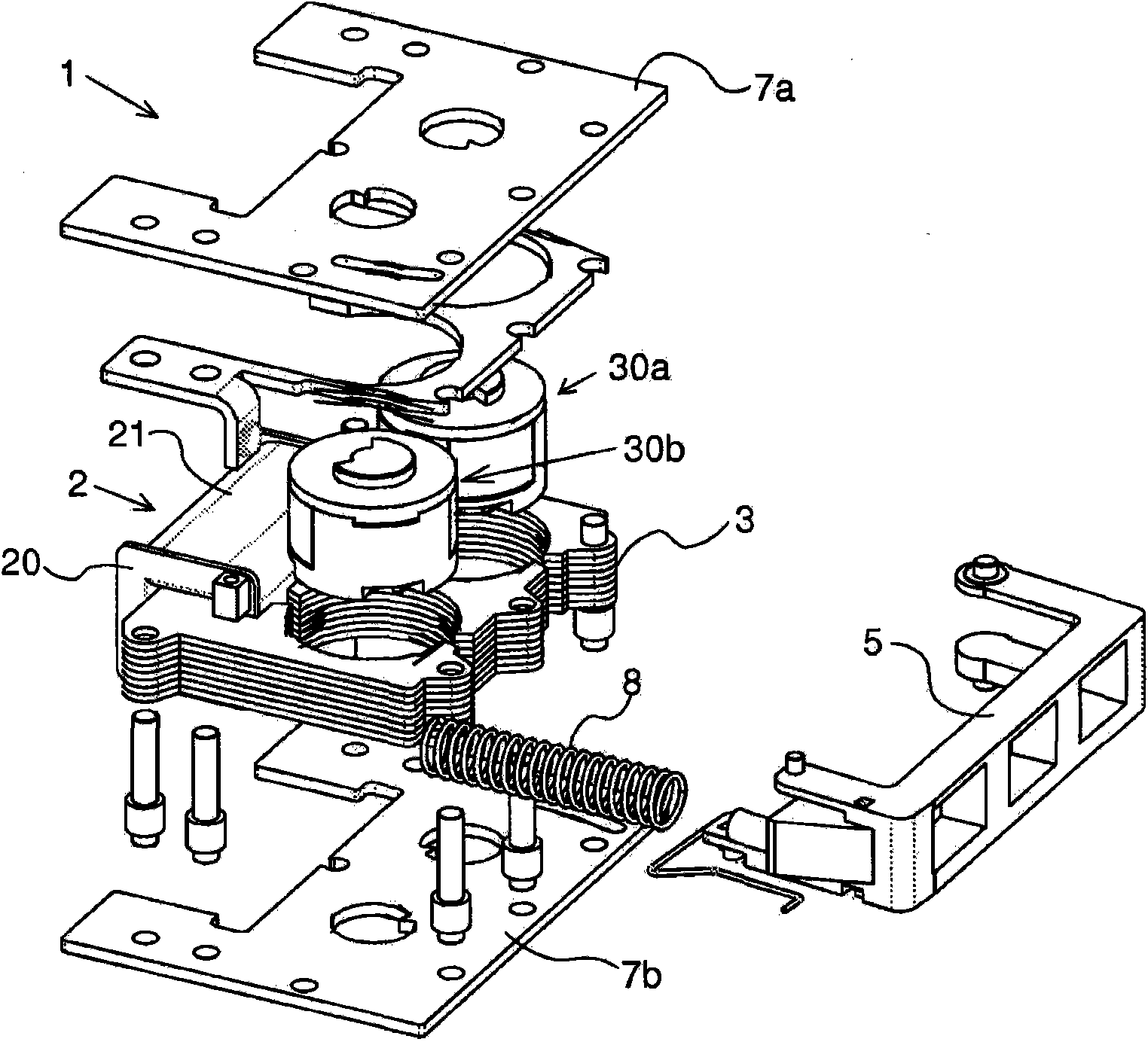
[0032] The stand-alone electrical energy generating device 1 according to the invention can be used to generate a current in the excitation coil 2 by external mechanical action, eg manually changing the magnetic flux through the coil 2 .

[0033] Such a device 1 can be used for wireless control devices without an internal current source. The control means are actuated manually, for example by means of a toggle-type switch or a push-button-type switch capable of controlling electrical equipment, such as lights, and can be positioned in different positions in the room without restriction. The control device comprises mechanical subassemblies (not shown) intended to receive an independent energy generating device 1 and electronic circuits powered by the energy generating device. This electronic circuit (not shown) typically includes means, such as capacitors, for storing the electrical energy generated by the device 1 according to the invention, so that the amount of current can ...


PUM


Abstract

The invention relates to a power generation device (1) that includes an excitation coil (2) with a central opening, and a magnetic circuit (3) extending through the central opening of the coil and including at least one permanent magnet (4a, 4b, 6) and a plurality of ferromagnetic members (33, 34, 32, 40) arranged in a fixed portion and two mobile portions (30a, 30b), characterized in that the two mobile portions (30a, 30b) are mounted on two parallel rotary axes and can each assume two positions, in that the device includes means for rotating (5, 50) the two mobile portions (30a, 30b) between the two positions thereof so as to create two states of the magnetic circuit (3), i.e. a first state in which a magnetic flow (F1) flows through the coil in one direction and a second state in whicha magnetic flow (F2) flows through the coil in the opposite direction.

Description

technical field [0001] The present invention relates to energy generating devices for converting mechanical energy into electrical energy. The invention also relates to a wireless stand-alone control device incorporating an energy generating device. Background technique [0002] Patent application WO2004 / 093299 discloses a converter for converting mechanical energy into electrical energy. The converter consists of permanent magnets and soft magnetic elements forming a magnetic circuit, and an electric coil surrounding a part of the magnetic circuit. The soft magnetic element and the permanent magnet are mounted to rotate relative to each other, which enables a change in flux to be produced in the magnetic circuit through the coil when one moves relative to the other, thereby generating a current in the coil. [0003] Document WO 2004 / 093299 provides the use of a converter in a stand-alone energy switch, that is to say without an energy source and wireless. When the switch...

Claims


Application Information

Patent Timeline
Patent Type & Authority Applications(China)
IPC IPC(8): H02K35/02H02K35/06
CPCH02K35/06H02K35/02H01H2239/076
Inventor 克里斯琴·巴塔伊迪迪尔·维古劳克斯
Owner SCHNEIDER ELECTRIC IND SAS
Why Eureka
Try Eureka