Heat pump with intercooler

a technology of intercooler and heat pump, which is applied in the direction of refrigeration machines, compression machines with reversible cycles, gas cycle refrigeration machines, etc., can solve the problems of less desirable provision of intercooler in the conventional refrigerant system, exceeding the limit, and extremely high refrigerant discharge temperature, etc., to achieve improved efficiency, increase system capacity, and improve cooling potential

Active Publication Date: 2010-02-11
CARRIER CORP
View PDF11 Cites 12 Cited by
  • Summary
  • Abstract
  • Description
  • Claims
  • Application Information

AI Technical Summary

Benefits of technology

[0008]When the system is operating in the cooling mode, the intercooler also increases system capacity and improves efficiency, since the compressor discharge temperature is reduced, and the outdoor heat exchanger (a condenser or a gas cooler, in this case) will be capable to cool refrigerant to a lower temperature, providing a higher cooling potential in the evaporator.
[0009]Additionally, if the system operates in a transcritical cycle, where the high side temperature and pressure are independent from each other, the discharge pressure is not limited by a discharge temperature anymore and can be adjusted to the value providing an optimum performance level. Thus, efficiency and capacity in both cooling and heating modes of operation are enhanced.

Problems solved by technology

If the compression ratio for the compressor system is high (which is typically the case for two-stage compression systems) and / or refrigerant suction temperature is high (which is often the case for a refrigerant system equipped with liquid-suction heat exchanger), then refrigerant discharge temperature can also become extremely high, and in many cases may exceed the limit defined by the safety or reliability considerations.
However, the additional cost of the circuitry and components associated with the intercooler, along with the limited benefits for the prior art refrigerant systems utilizing conventional refrigerants, made the provision of an intercooler in the conventional refrigerant systems less desirable.

Method used


Image

  • Heat pump with intercooler
  • Heat pump with intercooler

Examples


Embodiment Construction

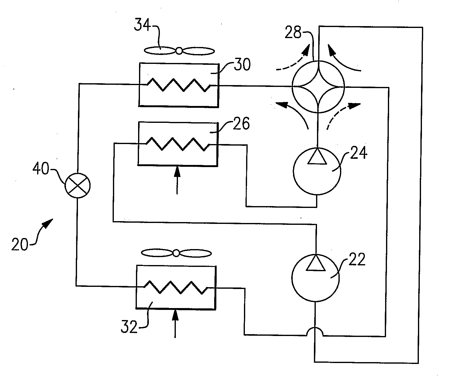
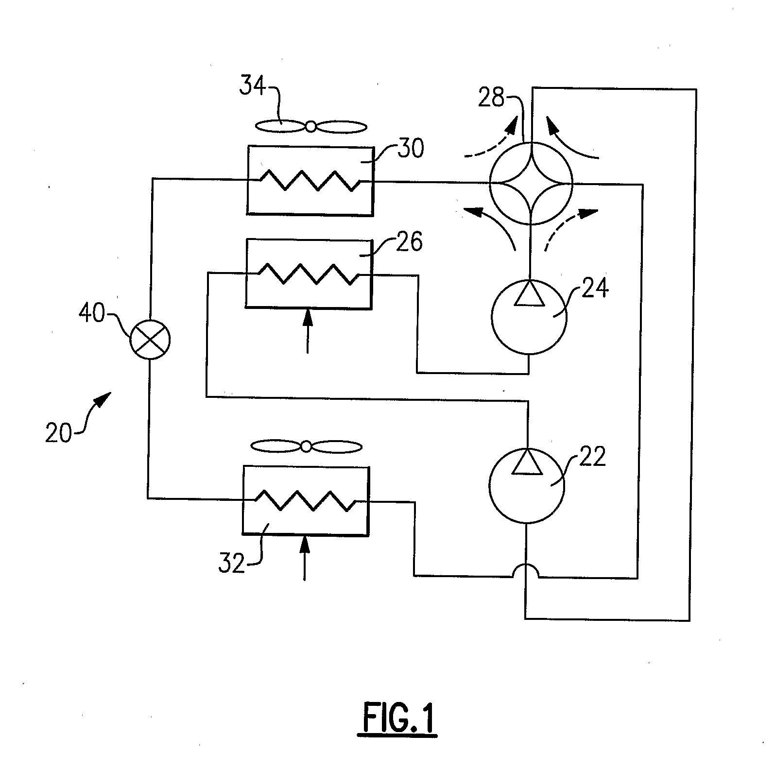
[0012]A refrigerant system 20 is illustrated in FIG. 1 having a lower stage compressor 22 and a higher stage compressor 24. While only two sequential stages are shown, additional stages may also be incorporated in series in this invention. Also, instead of separate compressors connected in sequence, a multi-stage compressor arrangement can be employed and equally benefit from the present invention. For instance, two separate compression members may be represented by different banks of cylinders connected in series for a reciprocating compressor. As known, refrigerant compressed by a lower stage to an intermediate pressure is delivered from a discharge outlet of this lower stage to the suction inlet of the higher stage. An intercooler 26 is positioned between the two stages to accept refrigerant from a discharge outlet of the lower stage 22, cool it by a secondary media, such as ambient air blowing over external heat transfer surface of the intercooler 26 during heat transfer interac...


PUM


Abstract

A heat pump refrigerant system is provided with at least two sequential stages of compression. An intercooler is positioned intermediate the two stages. The refrigerant flowing through the intercooler. is cooled by a secondary fluid such as ambient air. The intercooler is positioned to be in a path of air flow passing over an outdoor heat exchanger, and preferably upstream of the outdoor heat exchanger, in relation to this air flow. Benefits with regard to efficiency and capacity are achieved due to proposed system configuration in both heating and cooling modes of operation, while no additional circuitry or components are required to provide the intercooler function for the heat pump refrigerant system. This invention is particularly important for the CO2 heat pump refrigerant systems operating in the transcritical cycle.

Description

BACKGROUND OF THE INVENTION[0001]This application relates to a heat pump refrigerant system, wherein the compressor is a two-stage compressor, and wherein an intercooler is provided between the two compression stages. The intercooler is preferably subjected to the ambient airflow and is placed upstream of an outdoor heat exchanger with, respect to this ambient airflow, such that the cooling in the intercooler is preferably provided by the circuitry and components that are already part of the refrigerant system.[0002]Heat pumps are known in the air conditioning art, and are utilized to provide both heating and cooling of a secondary fluid, such as air, delivered into an environment to be conditioned. A typical heat pump includes a compressor, an expansion device, an outdoor heat exchanger and an indoor heat exchanger. Typically, a four-way valve reverses the flow of refrigerant throughout the system between a cooling and heating mode of operation. The refrigerant flows from the compr...

Claims


Application Information

Patent Timeline
Patent Type & Authority Applications(United States)
IPC IPC(8): F25B13/00F25B1/10F25B1/00
CPCF25B1/02F25B1/04F25B1/10F25B2400/072F25B13/00F25B2309/061F25B2313/02741F25B9/008
Inventor LIFSON, ALEXANDERTARAS, MICHAEL F.
Owner CARRIER CORP
Why Eureka
Try Eureka