Data transfer

a data transfer and data technology, applied in data switching networks, instruments, frequency-division multiplexes, etc., can solve the problems of ineffective utilization of available bandwidth, error recovery, and limited data transfer rate between network nodes using conventional methods, so as to reduce delays and improve data transfer rate

Inactive Publication Date: 2013-02-14
BRIDGEWORKS LTD
View PDF3 Cites 12 Cited by
  • Summary
  • Abstract
  • Description
  • Claims
  • Application Information

AI Technical Summary

Benefits of technology

[0009]Such a method permits the installation of a node to be simplified. For example, a newly installed bridge in a bridging system between local storage area networks (SANs) can teach itself appropriate initial values, using simulations to compile a database of values, or arrive at suitable values for specific data transfer scenarios through iteration and self-adjustment, without requiring manual tuning of the parameters. Moreover, the method permits such a node to maintain a given, or optimum, level of performance by repeating the adjustment routine during data transfer.
[0013]For instance, where the determination is based on whether a message relating to the first batch has been received from the second node, the transmission of the second batch of data packets can be initiated before such a message is expected to be received, in order to reduce delays and improve data transfer rate.
[0014]A plurality of connections may be used in a periodic sequence. The connections may be configured so that the time taken for each cycle of the sequence is related to the round trip time between the first and second nodes. For example, where the determination of whether the first batch of packets has been received is made based on the receipt or non-receipt of an acknowledgement (ACK) message from the second node, the first node may be arranged to transmit data via the second and subsequent connections, so that further batches of data packets can be transmitted without having to wait for an ACK message for the first batch to be received. In another example, the determination may be based on the receipt or non-receipt of a negative acknowledgement (NACK) message.

Problems solved by technology

The rate at which data can be transferred between network nodes using conventional methods can be limited by a number of factors.
Moreover, the amount of data may exceed the size of the receive buffer, causing error-recovery problems.
However, if the TCP / IP window is relatively small, the available bandwidth might not be utilised effectively.
Furthermore, the second node will be required to send a greater number of ACK messages, thereby increasing network traffic.
However, this transmission is subject to a limited data transfer rate.
However, the Fibre Channel Protocol (FCP) cannot be used over distances greater than 10 km, although a conversion to TCP / IP traffic can be employed to extend the distance limitation.

Method used


Image

  • Data transfer
  • Data transfer
  • Data transfer

Examples


Embodiment Construction

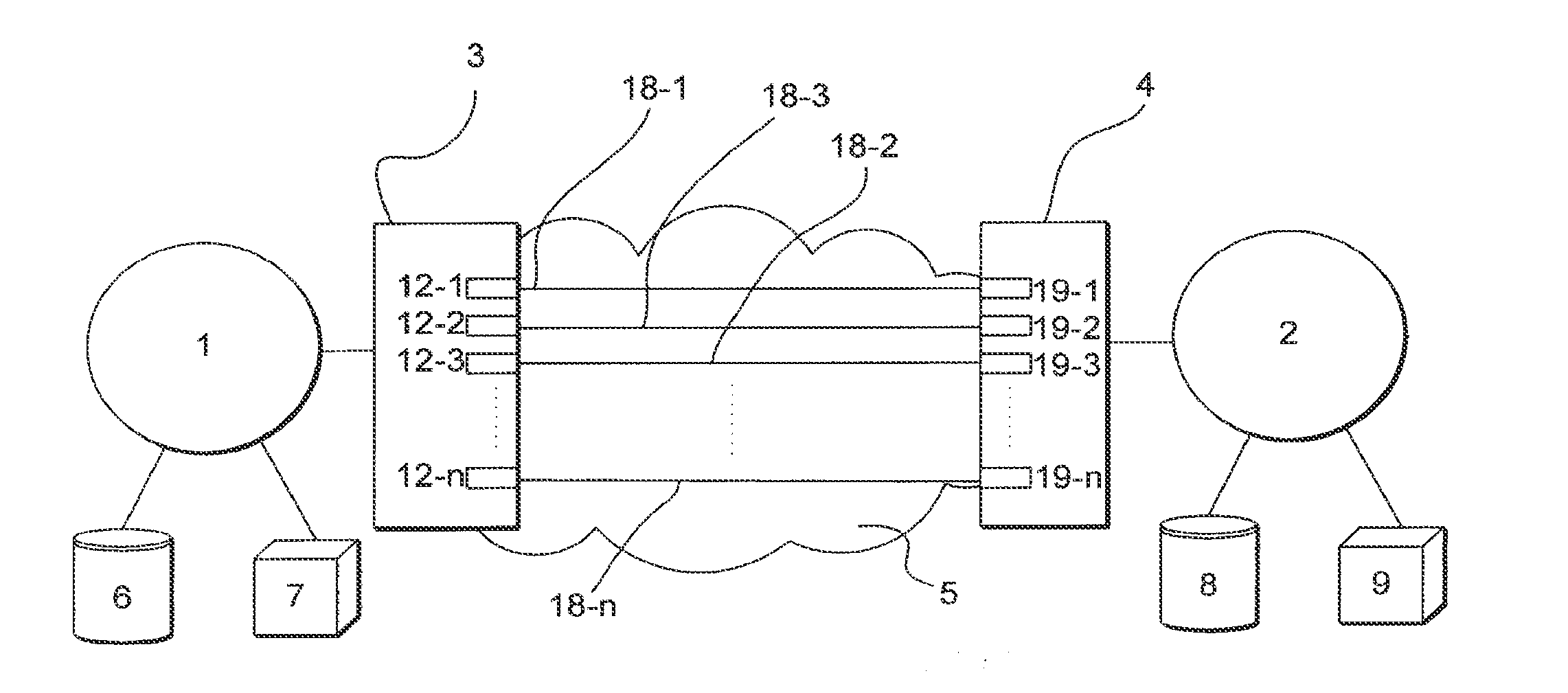
[0031]FIG. 1 depicts a system according to an embodiment of the invention. In this particular example, the system includes a local Storage Area Network (SAN) 1, a remote SAN 2. The remote SAN 2 is arranged to store back-up data from clients, servers and / or local data storage in the local SAN 1.

[0032]Two bridges 3, 4, associated with the local SAN 1 and remote SAN 2 respectively, are connected via a network 5. In this particular example, the network 5 is an IP network and the bridges 3 and 4 can communicate with each other using the Transmission Channel Protocol (TCP). The communication links between the bridges 3, 4 may include any number of intermediary routers and / or other network elements. Other devices 6, 7 within the local SAN 1 can communicate with devices 8 and 9 in the remote SAN 2 using the bridging system formed by the bridges 3,4 and network 5.

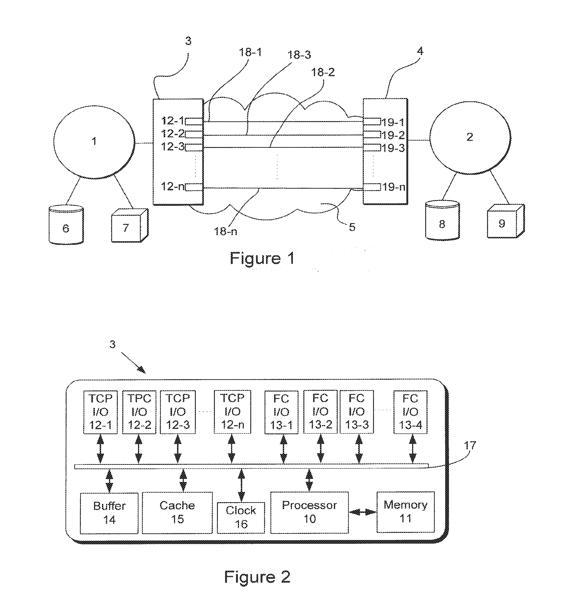
[0033]FIG. 2 is a block diagram of the local bridge 3. The bridge 3 comprises a processor 10, which controls the operation of the ...


PUM


Abstract

A bridging system, comprising bridges and a network, is arranged to transfer data using TCP / IP or similar between a local Storage Area Network (SAN) and a remote SAN. In one embodiment, a bridge is arranged to transfer data from a plurality of ports in a periodic sequence. While an acknowledgement from the remote SAN for data transferred from one port data is awaited, further data can be transferred using one or more of the remaining ports. In other embodiments, one or more parameters, such as number of ports, Receive Window Size etc., can be optimised using artificial intelligence (AI) routines in order to control the data transfer rate between the bridges. The bridging system may be configured to perform a self-learning routine on installation and, in some embodiments, to compile and consult a knowledge base storing optimum configurations for transferring data packets having different attributes by simulating data transfers.

Description

CROSS REFERENCE TO RELATED APPLICATIONS[0001]This application is a continuation of and claims priority to co-pending U.S. patent application Ser. No. 12 / 263,773, titled “Data Transfer” and filed on Nov. 3, 2008. U.S. patent application Ser. No. 12 / 263,773, is hereby incorporated by reference in its entirety.FIELD OF THE INVENTION[0002]The invention relates to a method and apparatus for transferring data.BACKGROUND OF THE INVENTION[0003]The rate at which data can be transferred between network nodes using conventional methods can be limited by a number of factors. In order to limit network congestion, a first node may be permitted to transmit only a limited amount of data before an acknowledgement message (ACK) is received from a second, receiving, node. Once an ACK message has been received by the first node, a second limited amount of data can be transmitted to the second node. In Transmission Control Protocol / Internet Protocol (TCP / IP) systems, that limited amount of data relates ...

Claims


Application Information

Patent Timeline
Patent Type & Authority Applications(United States)
IPC IPC(8): H04L12/26
CPCH04L1/1607H04L45/24H04L45/245H04L47/10H04L47/125H04L69/165H04L47/283H04L2001/0094H04L67/1097H04L69/16H04L69/14H04L47/27H04L1/0001H04L1/16H04L1/1803
Inventor TROSSELL, DAVIDHIBELL, LEWIS
Owner BRIDGEWORKS LTD
Why Eureka
Try Eureka