
Backlight module

A technology for a backlight module and a light source assembly, which is applied to the field of backlight modules with deviations in assembly positions, can solve the problems of increasing the energy loss of light-emitting diodes 122, poor contact between a flexible circuit board and a connector, and uneven brightness and darkness of a liquid crystal display panel, Achieve the effect of avoiding assembly position deviation, avoiding uneven light and dark, and saving material costs

Inactive Publication Date: 2011-02-09
AU OPTRONICS CORP
View PDF0 Cites 0 Cited by
  • Summary
  • Abstract
  • Description
  • Claims
  • Application Information

AI Technical Summary

Problems solved by technology

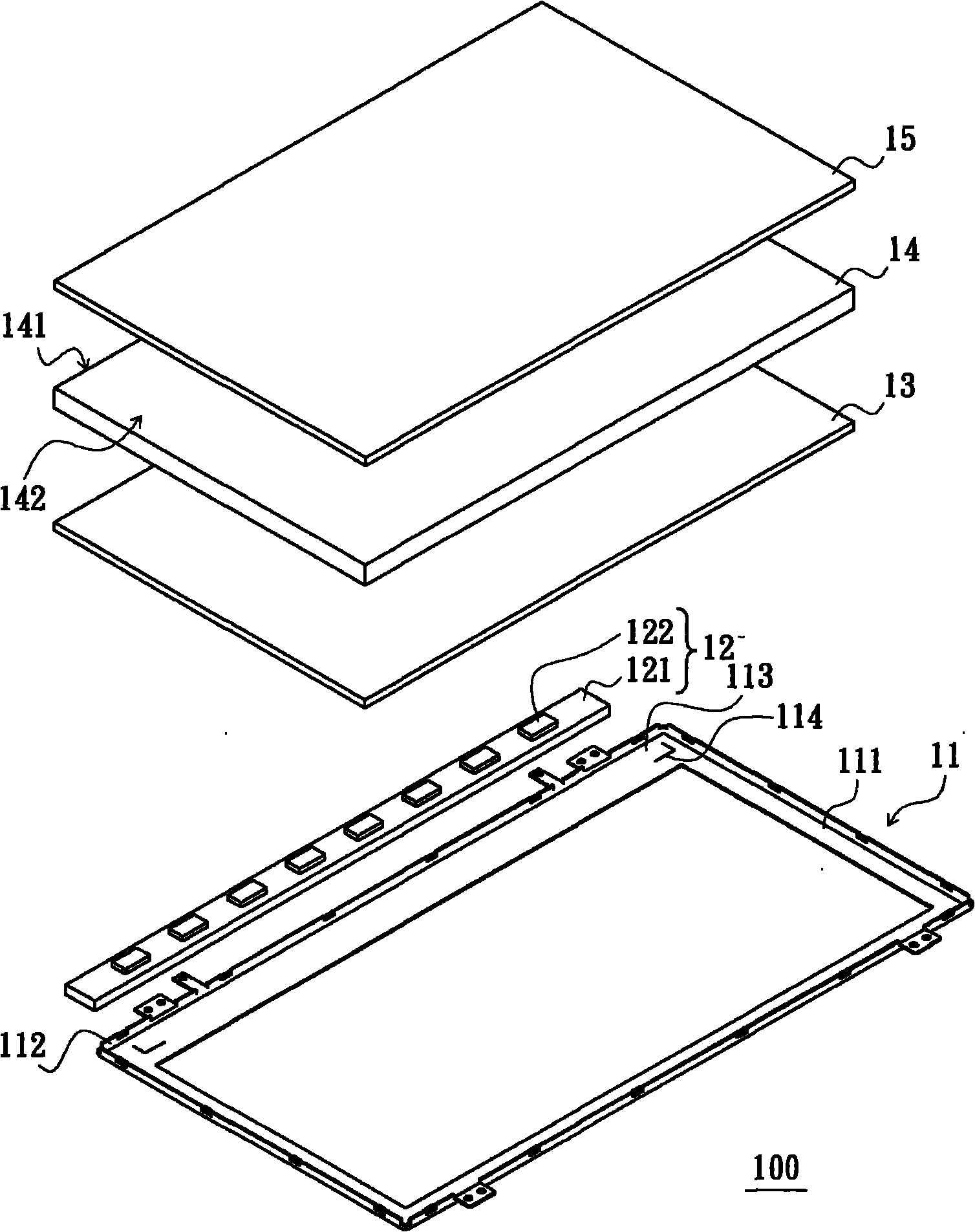
[0008] 1. The relative position of the light source assembly 12 and the light guide plate 14 is shifted, so that the light guide plate 14 cannot effectively convert the light emitted by the light emitting diode 122 into a surface light source with uniform brightness
[0009] 2. Since the light emitted by the light emitting diode 122 cannot be converted into a uniform surface light source, when the backlight module 100 is applied to a liquid crystal display, it may cause uneven brightness and darkness on the liquid crystal display panel (Mura phenomenon)
[0010] 3. The offset of the relative position between the light source assembly 12 and the light guide plate 14 will increase the energy loss of the light emitted by the light emitting diode 122 and reduce the light utilization rate
[0011] 4. When the backlight module 100 is applied to a liquid crystal display, the light source assembly 12 is connected to the connector of the driving circuit board of the liquid crystal display through a flexible circuit board (FPCB). The deviation of the position of the light source assembly 12 may cause the flexible circuit board (FPCB) to Poor contact of the connector

Method used


Image

  • Backlight module
  • Backlight module
  • Backlight module

Examples


Embodiment Construction

[0049] In order to further explain the technical means and effects of the present invention to achieve the intended purpose of the invention, the specific implementation, structure, features and effects of the backlight module proposed according to the present invention will be described in detail below in conjunction with the accompanying drawings and embodiments. As later.

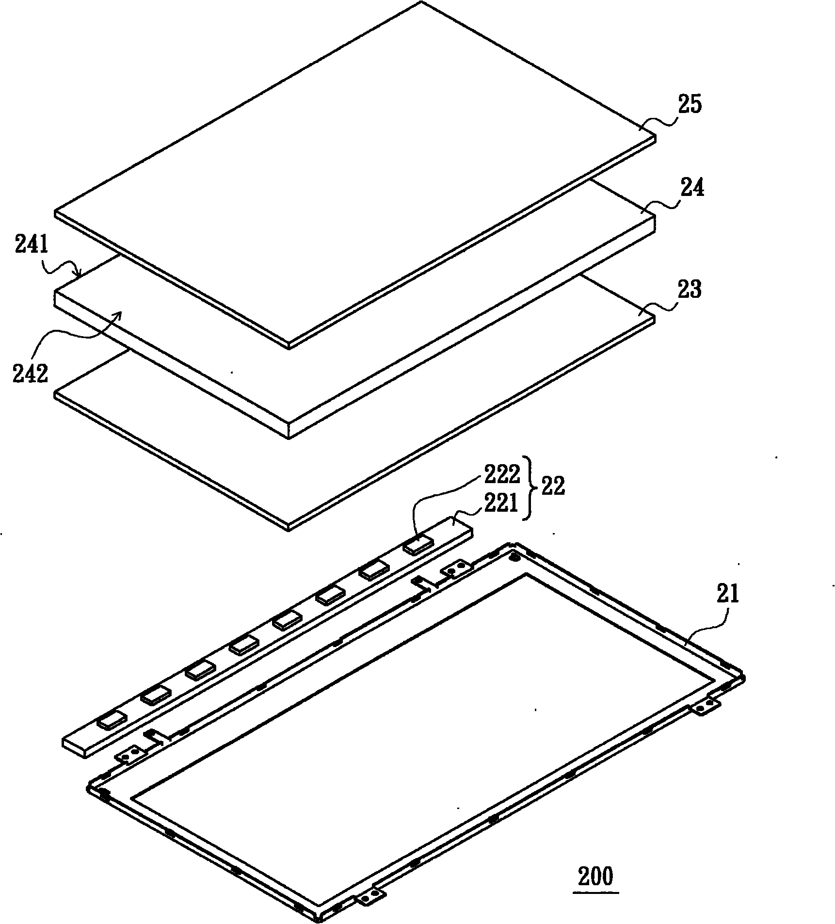
[0050] See figure 2 , the backlight module 200 is an edge-lit backlight module, which includes a frame 21 and a light source assembly 22 .

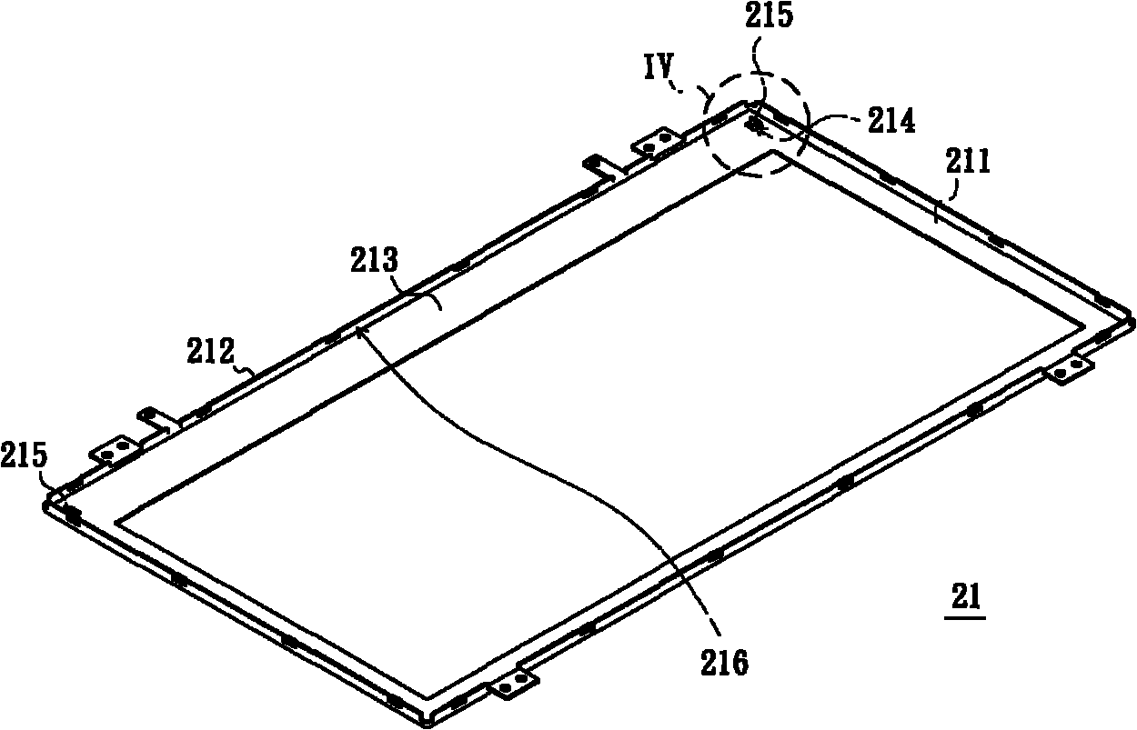
[0051] See image 3 and Figure 4 , the frame 21 includes a bottom plate 211 and a side wall 212 connected to an edge of the bottom plate 211 . The material of the frame 21 includes metal, such as aluminum or its alloys, or magnesium or its alloys, for example. The bottom plate 211 has a light source carrying portion 213 , and two opposite ends of the light source carrying portion 213 respectively define through holes 214 . A blocking piece 215 extends from an...


PUM


Abstract

The invention relates to a backlight module comprising a frame and a light source assembly, wherein the frame comprises a base plate and a side wall, wherein the side wall is connected with the edge of the base plate; the base plate is provided with a light source bearing part; the light source bearing part is provided with two through holes; a separation blade extends out of the inner side wall of each through hole; the light source assembly is configured on the light source bearing part; and two opposite ends of the light source bearing part are abutted between two separation blades. The backlight module can effectively prevent the assembling position of the light source assembly from being deviated.

Description

technical field [0001] The invention relates to a backlight module, in particular to a backlight module capable of preventing the deviation of the assembly position of a light source component. Background technique [0002] The liquid crystal display panel of the liquid crystal display cannot emit light by itself, so there must be an external light source to provide the surface light source required by the liquid crystal display panel. The backlight module plays the role of providing surface light source in the liquid crystal display, so the backlight module is one of the important components of the liquid crystal display. [0003] A conventional backlight module 100 includes a frame 11 , a light source assembly 12 , a reflection sheet 13 , a light guide plate 14 and an optical film 15 . [0004] The frame 11 includes a bottom plate 111 and side walls 112 connected to edges of the bottom plate 111 . The bottom plate 111 has a light source carrying portion 113 , and two opp...

Claims


Application Information

Patent Timeline
Patent Type & Authority Applications(China)
IPC IPC(8): G02F1/13357F21S8/00F21V19/00F21V8/00F21Y101/02
Inventor 许子辉黄启祥王崇权
Owner AU OPTRONICS CORP
Learn More