Electric wetting lens and forming method thereof

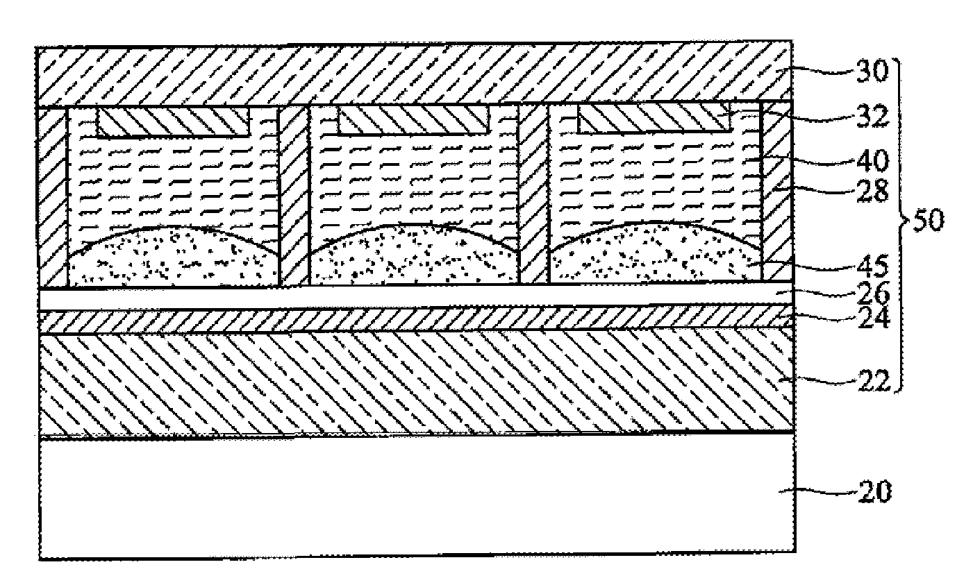
An electro-wetting lens and electrode technology, which is applied to lenses, optics, instruments, etc., can solve problems such as positional deviation of the assembled and aligned retaining wall structure 28, damage to the retaining wall structure 28, etc., so as to reduce the requirements of dripping accuracy and yield. High, avoid the effect of group position deviation

Inactive Publication Date: 2011-11-23
KUSN INFOVISION OPTOELECTRONICS
View PDF7 Cites 23 Cited by
  • Summary
  • Abstract
  • Description
  • Claims
  • Application Information

AI Technical Summary

Problems solved by technology

In the existing process of forming the retaining wall structure 28 first and then assembling the first substrate 30 and the second substrate 22, instilling the polar liquid 40 and the non-polar liquid 45 requires parameters such as instillation position and instillation volume in the process. Moreover, in the process of forming the retaining wall structure 28, the position deviation of the retaining wall structure 28 or the defect of damaging the retaining wall structure 28 caused by the problem of assembly and alignment are prone to occur.

Method used


Image

  • Electric wetting lens and forming method thereof
  • Electric wetting lens and forming method thereof
  • Electric wetting lens and forming method thereof

Examples


Embodiment Construction

[0018] In order to make the above objects, features and advantages of the present invention more comprehensible, specific implementations of the present invention will be described in detail below in conjunction with the accompanying drawings.

[0019] It should be noted that, for the sake of clarity of illustration, the drawings of the present invention only show structural features related to the inventive point of the present invention, while other structural features are omitted.

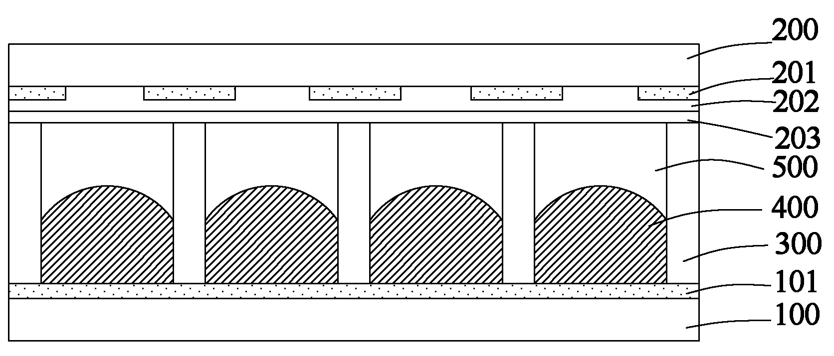
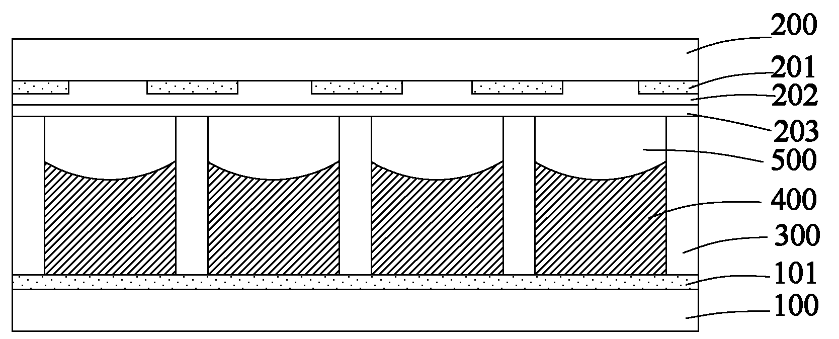
[0020] figure 2 with image 3 A partial cross-sectional schematic diagram of an electrowetting lens that discloses a specific embodiment of the present invention, as shown in figure 2 with image 3 As shown, an electrowetting lens according to a specific embodiment of the present invention includes a first substrate 100 and a second substrate 200 oppositely arranged, wherein a first transparent electrode 101 is arranged on the first substrate 100; A second transparent electrode 201 and a di...


PUM


Abstract

The invention discloses an electric wetting lens and a forming method thereof. The forming method comprises the following steps of: providing a first substrate and forming a first transparent electrode on the first substrate; providing a second substrate and forming a second transparent electrode on the second substrate; forming a dielectric layer on the second transparent electrode; oppositely assembling the first substrate and the second substrate; clamping a polar liquid with photopolymerisable matters and a non-polar liquid with photopolymerisable matters between the first substrate and the second substrate; and irradiating the first substrate and the second substrate which are assembled to solidify the photopolymerisable matters in the polar liquid and the non-polar liquid so as to form a retaining wall structure between the first substrate and the second substrate. The electric wetting lens has the advantages of simplicity in preparation process and high product yield.

Description

technical field [0001] The invention relates to the field of display technology, in particular to a method for forming an electrowetting lens and the electrowetting lens. Background technique [0002] Electrowetting (Electrowetting) is a microfluidic phenomenon. Using electrowetting or electrocapillary (Electrocapillary) phenomenon, when a polar fluid is subjected to an electric field, the surface shape of the fluid is changed, making the surface distribution of the polar fluid changes happened. Electrowetting technology has begun to be widely used as a driving mechanism for various fluidic and electro-optic devices. The liquid lens using the electrowetting phenomenon, like the human eye, can automatically adapt to the object it is aiming at without the assistance of a mechanical device. It only needs to change the voltage of the two poles to modify the shape of the liquid to achieve the purpose of focusing and zooming. . Compared with traditional lenses, electrowetting l...

Claims


Application Information

Patent Timeline
Patent Type & Authority Applications(China)
IPC IPC(8): G02B3/14G02B26/02
Inventor 陈超平乔艳冰
Owner KUSN INFOVISION OPTOELECTRONICS
Why Eureka
Try Eureka