Method for visually monitoring fracture crack

A fracturing and fracture technology, applied in the field of visual monitoring of fracturing fractures, can solve problems such as high cost, fracture development and damage, and damage.

Inactive Publication Date: 2011-02-09
CHINA UNIV OF PETROLEUM (BEIJING)
View PDF4 Cites 63 Cited by
  • Summary
  • Abstract
  • Description
  • Claims
  • Application Information

AI Technical Summary

Problems solved by technology

For example: an existing observation method is to split the sample with hacksaw, iron brazing and other tools after fracturing the rock sample, so as to observe the shape of the crack; In the process of sampling, the original fracturing fractures will inevitably be destroyed, or new cracks will be generated on the basis of the original cracks, which will greatly affect the accuracy of the experimental results; secondly, in the observation of multiple fractures, The existing observation method after fracturing is to split the sample along the main fracture, and the result can only be the observation of the main fracture surface, while the development of other fractures is destroyed
This type of technology can visually observe the expansion shape of the crack; but the cost is high and the operation is difficult

Method used


Image

  • Method for visually monitoring fracture crack
  • Method for visually monitoring fracture crack
  • Method for visually monitoring fracture crack

Examples


Embodiment approach 1

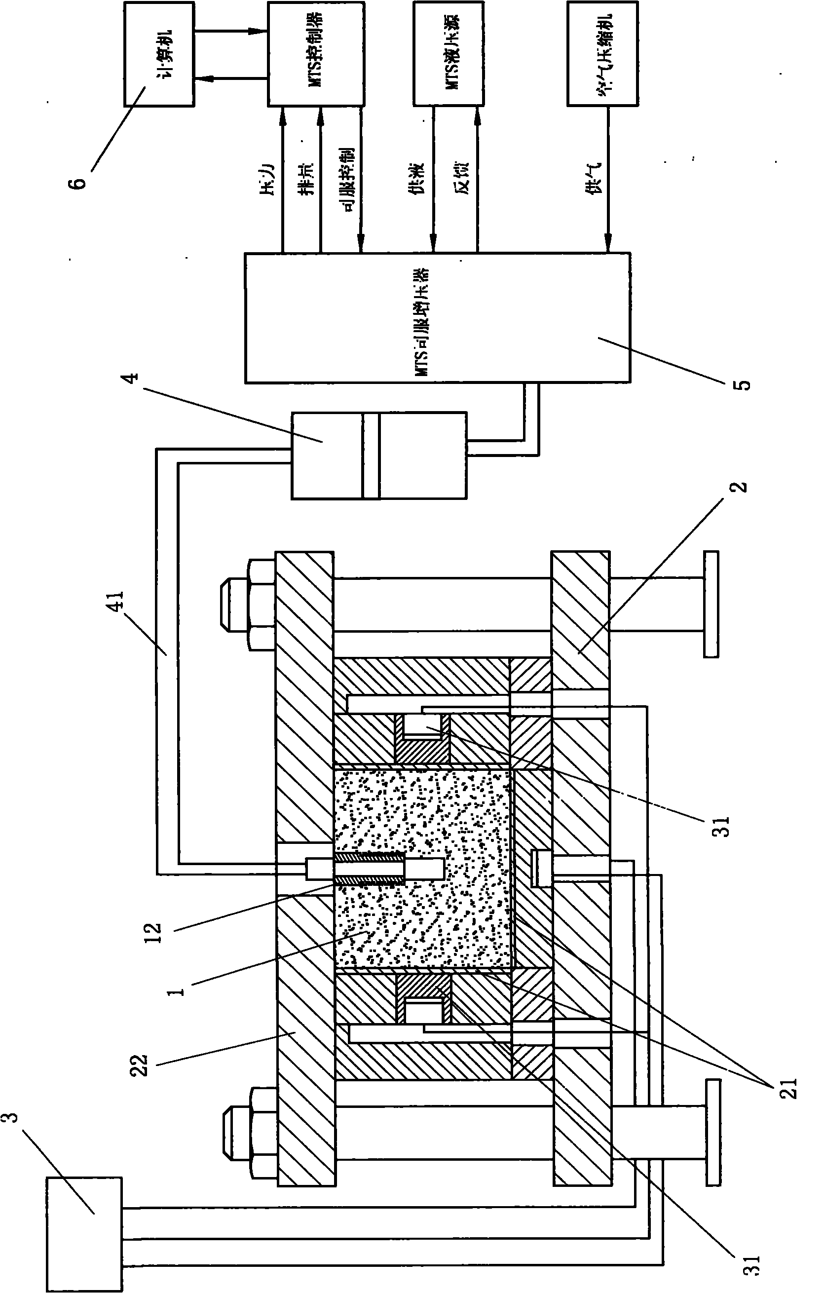
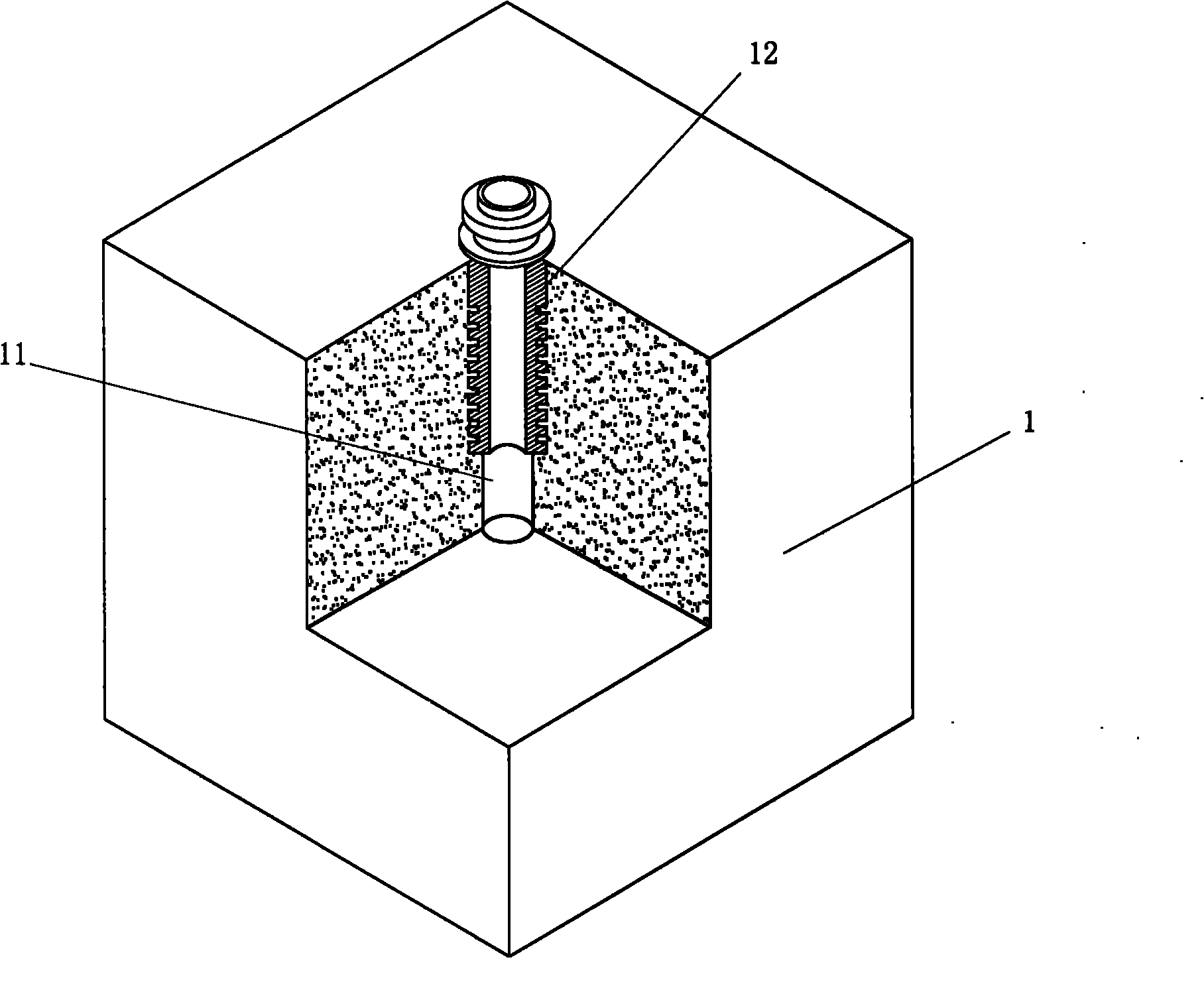
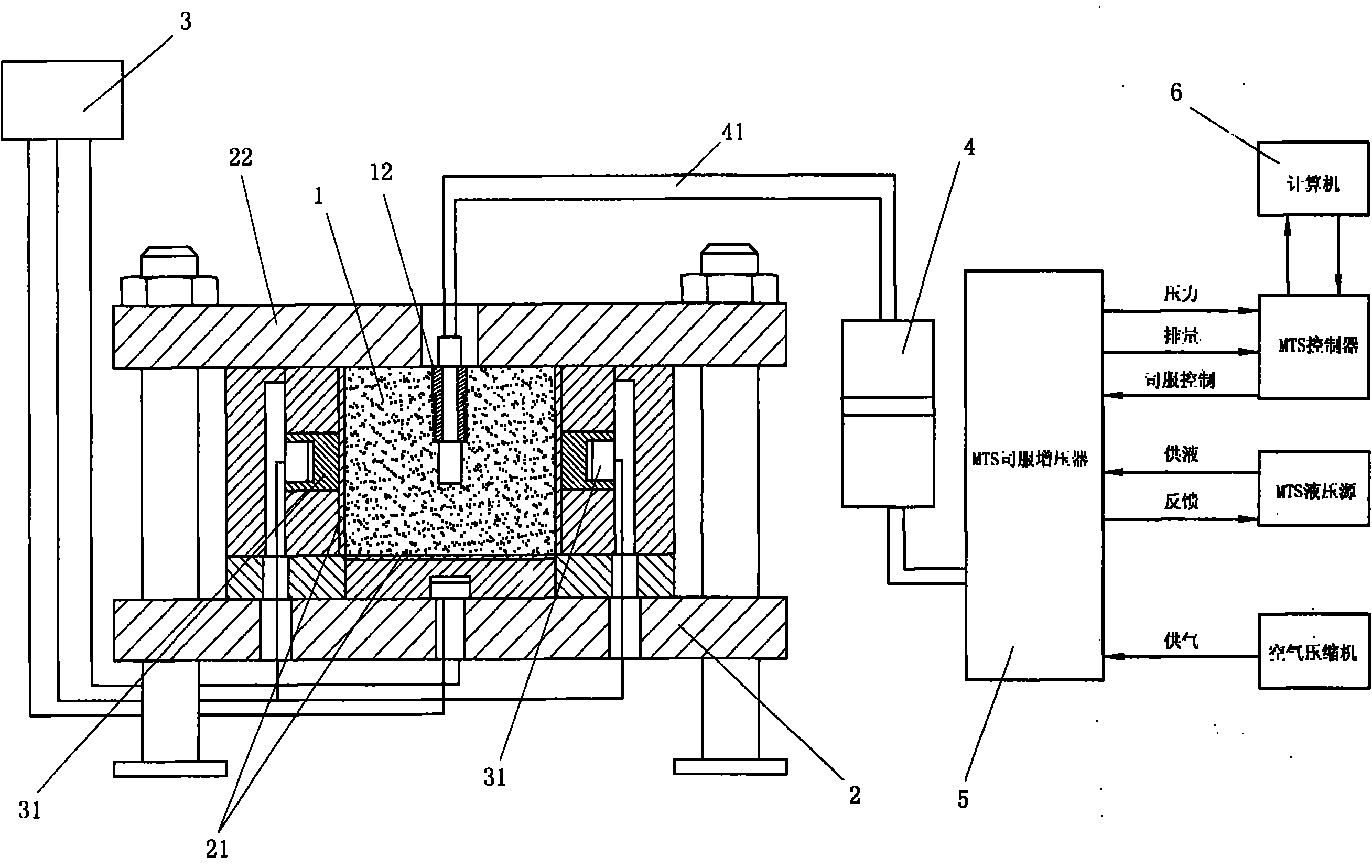
[0029] The present invention proposes a method for visually monitoring fracturing fractures. The method uses a room-temperature-curable fluid material as a fracturing fluid, injects the fluid material into a simulated wellbore of a core sample, and generates cracks when the core sample is fractured. At the same time, the room temperature curing fluid material is filled into the crack and filled with the crack, and after the room temperature curing fluid material is solidified to form a simulated crack, the simulated crack is taken out and the shape of the simulated crack is observed;

[0030] In this embodiment, the room temperature curing fluid material is a two-component liquid silica gel at room temperature; the two-component liquid silica gel at room temperature is composed of SYLGARD184 liquid silica gel mixed with a catalyst; the SYLGARD184 liquid silica gel has lower viscosity and Strong tensile strength, elongation at break and tear strength, operating time is 2 hours. ...

Embodiment approach 2

[0046] The principle and structure of this embodiment and Embodiment 1 are basically the same, the difference is that in this embodiment, silicone oil is injected into the simulated wellbore 12 of the core sample 1 as a fracturing fluid, and the core sample 1 is fractured to produce After the fracture, the room temperature solidifying fluid material (that is: the aforementioned room temperature two-component liquid silica gel) is injected as a filling material into the simulated wellbore 12 of the core sample 1, so that the liquid silica gel is filled into the fracture to replace the The silicone oil is filled with the cracks, and after the liquid silicone solidifies to form simulated cracks, the simulated cracks are taken out and the shape of the simulated cracks is observed.

[0047] In this embodiment, the silica gel used as the fracturing fluid is simethicone. The simethicone oil has physiological inertia, good chemical stability, electrical insulation and weather resistan...


PUM


Abstract

The invention relates to a method for visually monitoring a fracture crack, which comprises the steps of: with a room-temperature cured type fluid material as a fraction fluid, injecting the fluid material into a wellbore hole simulator of a core sample, filling the fluid material into the crack and fully filling into the crack when the core sample is fractured to generate the crack; and after the fluid material is cured to form a simulated crack, taking the simulated crack out and observing the form of the simulated crack. The prepared concrete core sample is subjected to a fracture test in an experiment room by selecting silicon oil and fluid silicon gel as the fracture fluid, and after the fracture fluid is filled into the fracture crack and cured, the silicon gel simulated crack is taken out, and the expansion form of the crack can be represented by observing the form of the simulated crack, therefore, the method for visually monitoring the fracture crack achieves the purpose of visualization.

Description

technical field [0001] The invention relates to a method for monitoring fracturing cracks, in particular to a method for visually monitoring fracturing cracks. Background technique [0002] Hydraulic fracturing is a major measure to enhance oil and gas recovery in oil and gas fields, and indoor hydraulic fracturing physical experiment simulation is an important means to understand fracture propagation during fracturing. At present, in the monitoring of fracturing fractures, although the traditional methods are feasible, they all have certain limitations, especially in the visual observation of fractures. For example: an existing observation method is to split the sample with hacksaw, iron brazing and other tools after fracturing the rock sample, so as to observe the shape of the crack; In the process of sampling, the original fracturing fractures will inevitably be destroyed, or new cracks will be generated on the basis of the original cracks, which will greatly affect the ...

Claims


Application Information

Patent Timeline
Patent Type & Authority Applications(China)
IPC IPC(8): G01B13/16
Inventor 陈勉金衍邱园侯冰
Owner CHINA UNIV OF PETROLEUM (BEIJING)
Why Eureka
Try Eureka