3D Visualization Method of Mine Working Conditions Based on Object-Message Tree

A message tree and object technology, applied in special data processing applications, instruments, electrical digital data processing, etc., can solve problems such as lack of intuition and fidelity, powerlessness, inconvenient working condition visualization, etc., to achieve flexible and convenient logical structure, state The judgment is simple and the effect is easy to achieve

Inactive Publication Date: 2017-01-25
TIANDI CHANGZHOU AUTOMATION +1
View PDF2 Cites 0 Cited by
  • Summary
  • Abstract
  • Description
  • Claims
  • Application Information

AI Technical Summary

Problems solved by technology

[0004] The second is to use two-dimensional graphics technology and configuration technology to display working conditions, which lacks intuition and fidelity
[0005] Third, for some mine 3D management and control software launched at home and abroad, it may also provide some working condition visualization functions, but it is either biased towards the GIS system, providing some simple display functions of individual equipment working conditions and personnel positions, or biased towards configuration software, which also lacks intuition and realism
[0006] Fourth, the existing technology is generally used to solve the visualization of the working conditions of a single device installed with sensors, which is not easy to realize the visualization of working conditions at the system level
If real-time high-simulation display of the working conditions of the various components of the complex production system is to be realized in the real 3D scene of the mine, it is necessary to describe the logical structure of the production system, and logical operations are required to judge the state, and the existing methods are insufficient.

Method used


Image

  • 3D Visualization Method of Mine Working Conditions Based on Object-Message Tree
  • 3D Visualization Method of Mine Working Conditions Based on Object-Message Tree
  • 3D Visualization Method of Mine Working Conditions Based on Object-Message Tree

Examples


Embodiment 1)

[0029] The object-message tree-based three-dimensional visualization method for mine operating conditions in this embodiment utilizes the object-message tree of the production system.

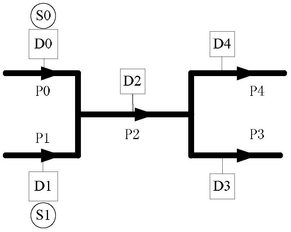
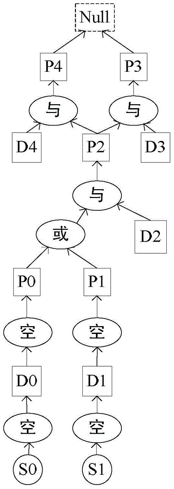
[0030] combine figure 1 and figure 2 , taking a mine nitrogen injection system (the system used for fire extinguishing in the mine) as an example to illustrate the meaning of object-oriented object-message tree: figure 1 As shown in the figure, D0 and D1 are two nitrogen generators, S0 and S1 are on-off sensors, D2-D4 are solenoid valve controllers, and P0-P4 are four-section pipelines. Now it is required to display the status of the entire nitrogen injection system in real time. Working conditions, including the start-stop state of the nitrogen generator, the switch state of the solenoid valve and the flow state of nitrogen in each pipeline. The object-message tree of the nitrogen injection system such as figure 2 As shown, the arrow in the figure indicates the direction of message transm...


PUM


Abstract

The invention provides a mine operating condition 3D visualization method based on an object-message tree. The method comprises the following steps of establishing a true 3D model of a mine, establishing connection with a monitoring data server, establishing a mapping relation between monitoring points and virtual objects in a scene, establishing an object-message tree of all production systems, establishing a visualization manager, establishing and starting a sound monitor, activating a corresponding virtual object, making the sound monitor continue to receive a next group of real-time monitoring data, breaking connection with the monitoring data server and then quitting an operating condition 3D visualization process. According to the mine operating condition 3D visualization method based on the object-message tree, the object-message tree is used for judging states of the virtual objects and transmitting state change messages, and the 3D real-time rendering technology and the sound-light alarm technology are used for realizing visualization of operating conditions of all the production systems of the mine; the object-message tree adopted in the method is of a flexible hierarchical structure, can describe any complex production system and the logical structure of internal devices of the production system, is easy to realize, and is particularly suitable for operating condition visualization of the production systems.

Description

technical field [0001] The invention relates to the technical field of computer three-dimensional visualization processing, in particular to a method for three-dimensional visualization of mine operating conditions based on an object-message tree by utilizing a true three-dimensional model of a mine production system. Background technique [0002] Traditional two-dimensional graphics technology and configuration technology have been widely used in the field of visualization of mine working conditions, but they have inherent defects of intuition and lack of authenticity, and cannot simulate the visualization of working conditions. With the upgrading of computer hardware equipment, especially the advent of various professional graphics cards, 3D visualization technology has begun to be applied to the visualization of mine working conditions, and has won people's favor for its high-simulation visualization effects, but the current application It is still in the initial stage, h...

Claims


Application Information

Patent Timeline
Patent Type & Authority Patents(China)
IPC IPC(8): G06F17/00G06Q50/02
Inventor 熊书敏陈和权张战国余谦张焕强孙晓东权洁
Owner TIANDI CHANGZHOU AUTOMATION
Why Eureka
Try Eureka