Compact injection device with reduced tendency to form vapor bubbles

A technology of injection devices and injectors, which is applied in the direction of fuel injection devices, charging systems, secondary air defueling, etc., and can solve problems such as large structural space and complex structures

Active Publication Date: 2011-02-09
ROBERT BOSCH GMBH
View PDF1 Cites 4 Cited by
  • Summary
  • Abstract
  • Description
  • Claims
  • Application Information

AI Technical Summary

Problems solved by technology

But the structure is relatively complex and

Method used


Image

  • Compact injection device with reduced tendency to form vapor bubbles
  • Compact injection device with reduced tendency to form vapor bubbles
  • Compact injection device with reduced tendency to form vapor bubbles

Examples


Embodiment Construction

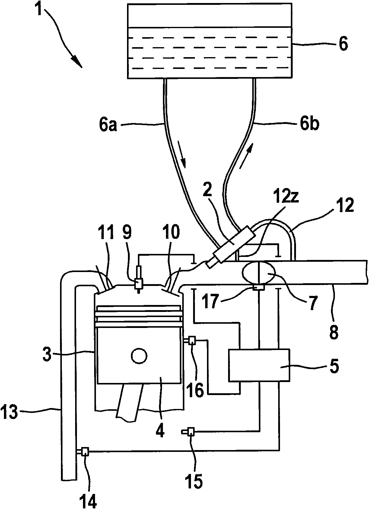
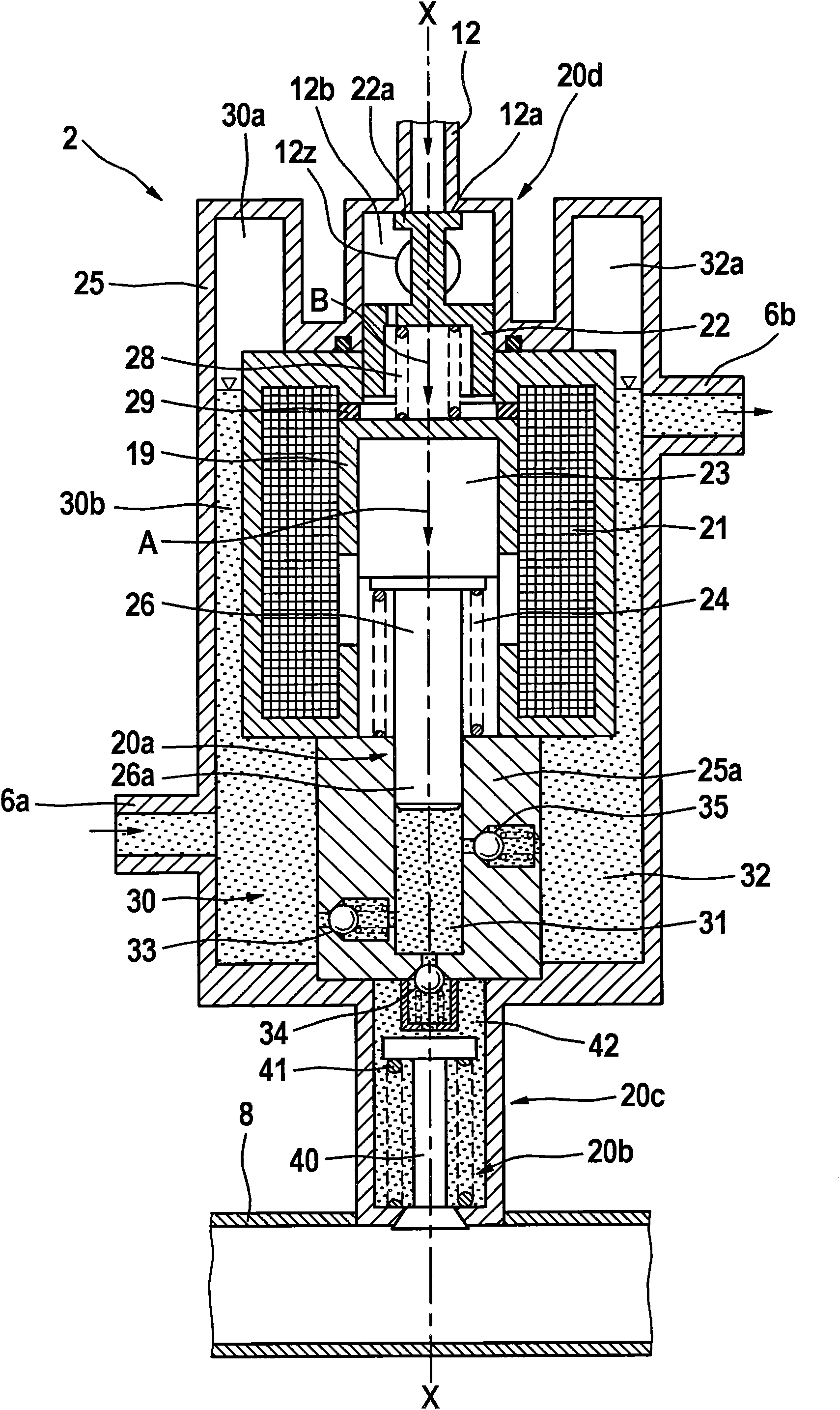
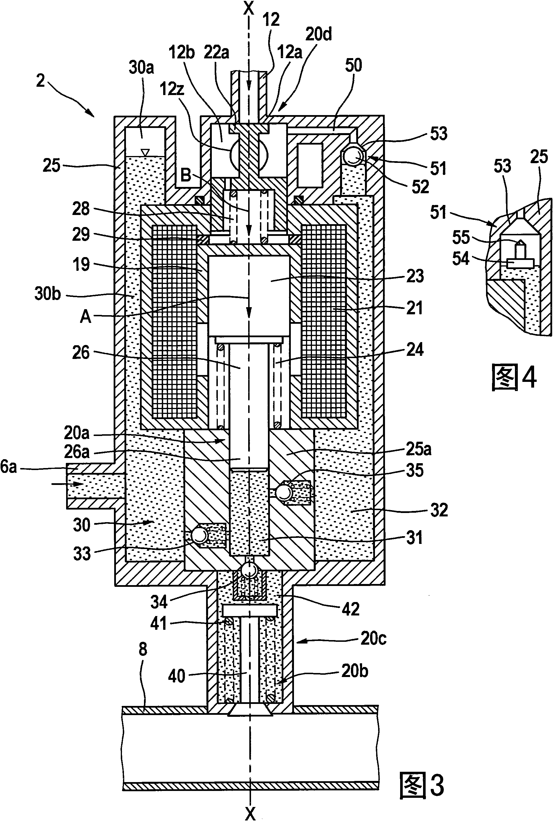
[0027] Refer below Figure 1 to Figure 4 A small engine 1 having an inventive injection device according to a first embodiment will now be described in detail.

[0028] figure 1 The structure of a small engine 1 is shown schematically, which is designed as a single-cylinder engine. The small engine 1 comprises a cylinder 3 , a piston 4 reciprocable in the cylinder, a control unit 5 and a container 6 . The container 6 is connected to the injection module 2 via a fuel feed line 6a. A fuel return line 6 b returns from the injection module 2 to the container 6 . Such as figure 1 As shown schematically in , the container 6 is arranged above the injection module 2 . As a result, the fuel flows via the fuel feed line 6a to the injection module 2 on the basis of gravity. The injection module 2 shown very schematically comprises a fuel pump, an injector with an integrated pressure regulator and an air conditioner, whereby the injection module 2 is constructed very compactly.

[...


PUM


Abstract

The present invention relates to an injection device comprising a fuel pump (20a), a pressure regulator (20b), an injector (20c) and an air adjuster (20d), characterized in that the fuel pump (20a), the injector (20c) and the air adjuster (20d) are integral components of an injection module (2), the pressure regulator (20b) is an integral component of the injector (20c) and the injection device comprises an intake chamber (30) which is an integral component of the injection module (2) and which is connected to a pump chamber (31) of the fuel pump by way of a first check valve (33), wherein a volume of the pump chamber (31) is smaller than a volume of the intake chamber (30) and wherein the intake chamber (30) comprises a gas-filled area (30a) and a fuel area (30b) for damping an intake pulsation in the intake chamber (30).

Description

technical field [0001] The invention relates to an injection device of compact design, which has a fuel pump, a pressure regulator, injectors and an air regulator. Background technique [0002] Injection devices are known from the prior art in various designs. Especially for reasons of cost and installation space, small internal combustion engines with only one or only two cylinders and a small displacement require separate solutions. Fields of application of such small internal combustion engines are, for example, two- or three-wheeled vehicles or lawnmowers or the like. Known injection devices generally include a fuel pump with a pressure regulator in a container, wherein the fuel pump delivers fuel with a predetermined pressure into a line, such as a common rail or the like. Injectors are arranged at the ends of the lines, which inject fuel into the intake manifold or directly into the combustion chamber in a controlled manner by the control unit. However, such an inje...

Claims


Application Information

Patent Timeline
IPC IPC(8): F02M37/20F02M23/06F02M57/02F02D9/10F02M51/04F02M55/04
CPCF02M57/027F02M37/20F02M51/04F02M55/04
Inventor G·霍尔U·西贝尔W·莫伊雷尔H·朗
Owner ROBERT BOSCH GMBH
Why Eureka
Try Eureka