Automobile shock absorber support projection welding floating tool

A technology of automobile shock absorber and shock absorber, which is applied in the direction of manufacturing tools, welding equipment, resistance welding equipment, etc., can solve the problems of severe shunt, unstable quality state, and large loss in the welding process, so as to reduce the cost of tooling and energy consumption, stable welding process quality, and stable welding strength

Inactive Publication Date: 2011-02-16
浙江鼎信航天科技有限公司
View PDF8 Cites 29 Cited by
  • Summary
  • Abstract
  • Description
  • Claims
  • Application Information

AI Technical Summary

Problems solved by technology

This adjustment method takes at least 1-2 hours for skilled operators, and for new employees, the time required for mold change is even as much as 4-6 hours, which seriously affects the production schedule;
[0008] 2. Unstable quality status: poor positioning accuracy: Since the welding process is a process of energizing and pressing parts, the bracket 801 is located on the upper electrode, and the oil cylinder assembly 802 is located on the lower electrode 2A, which is greatly affected by human factors; on the other hand The welding strength is unstable. Since the parts are respectively clamped on the upper and lower electrodes, rigid collision occurs during the welding process. The contact area of ​​the bump is small and the pressure is high. The bump is plastically deformed during the pre-pressing process, and the size of the bump changes. The welding strength is unstable ;
[0009] 3. The cost of tooling debugging is high: because the mold change process needs to be welded with a small current → measure the size and then re-adjust the position of the tooling, the parts in the debugging welding process cannot be re-welded, and all of them are scrapped, which increases the production cost of the product;
[0010] 4. High cost of tooling: Since 90% of the ma

Method used


Image

  • Automobile shock absorber support projection welding floating tool
  • Automobile shock absorber support projection welding floating tool
  • Automobile shock absorber support projection welding floating tool

Examples


Embodiment Construction

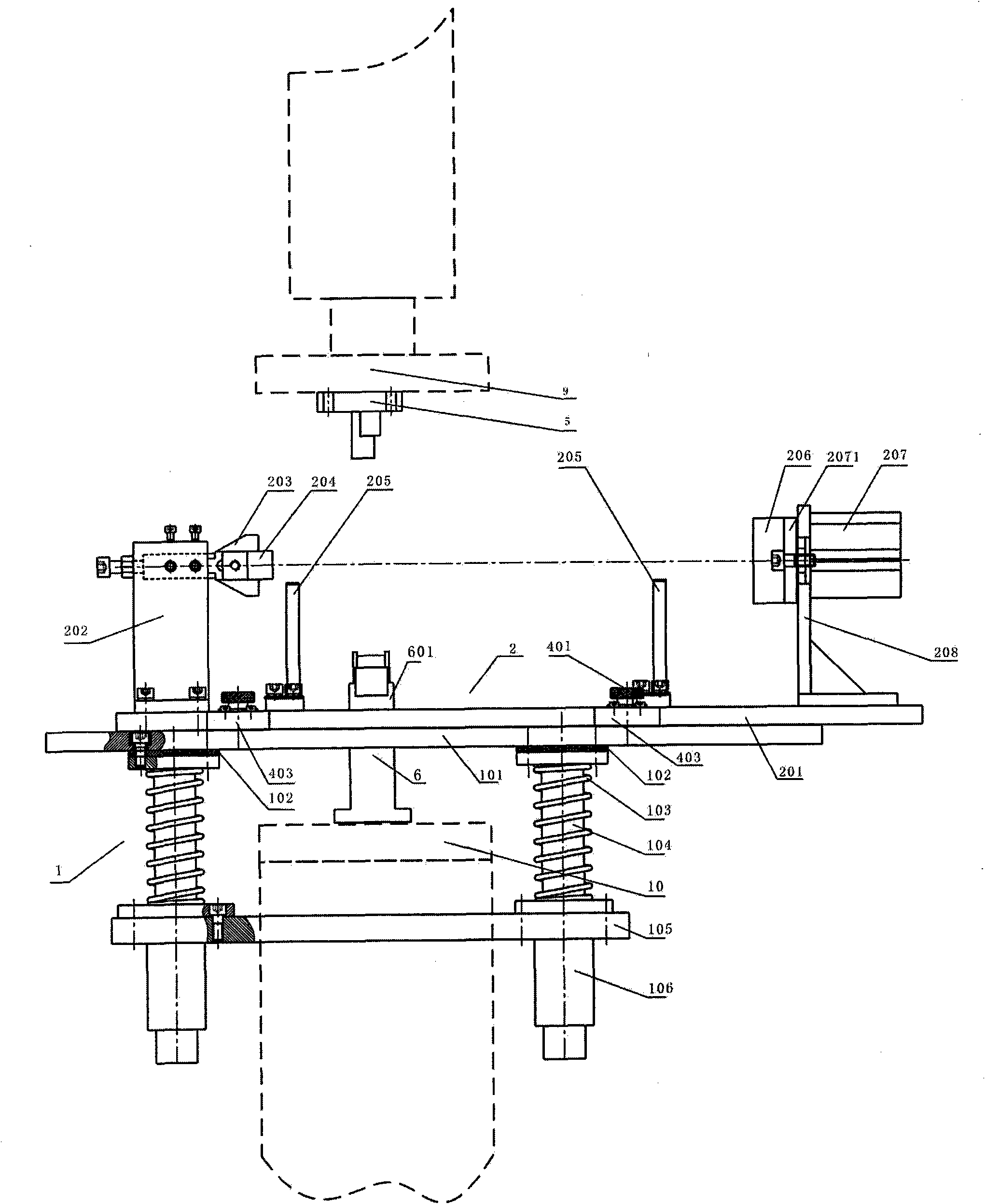
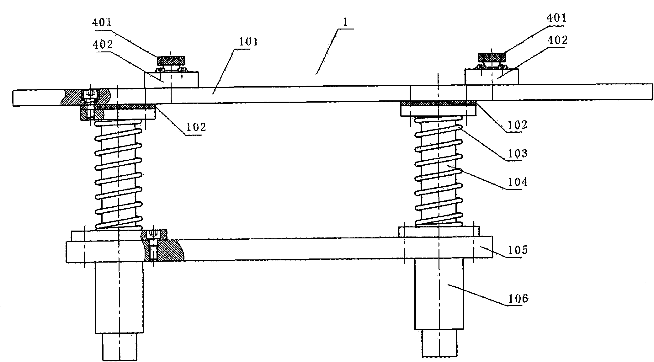
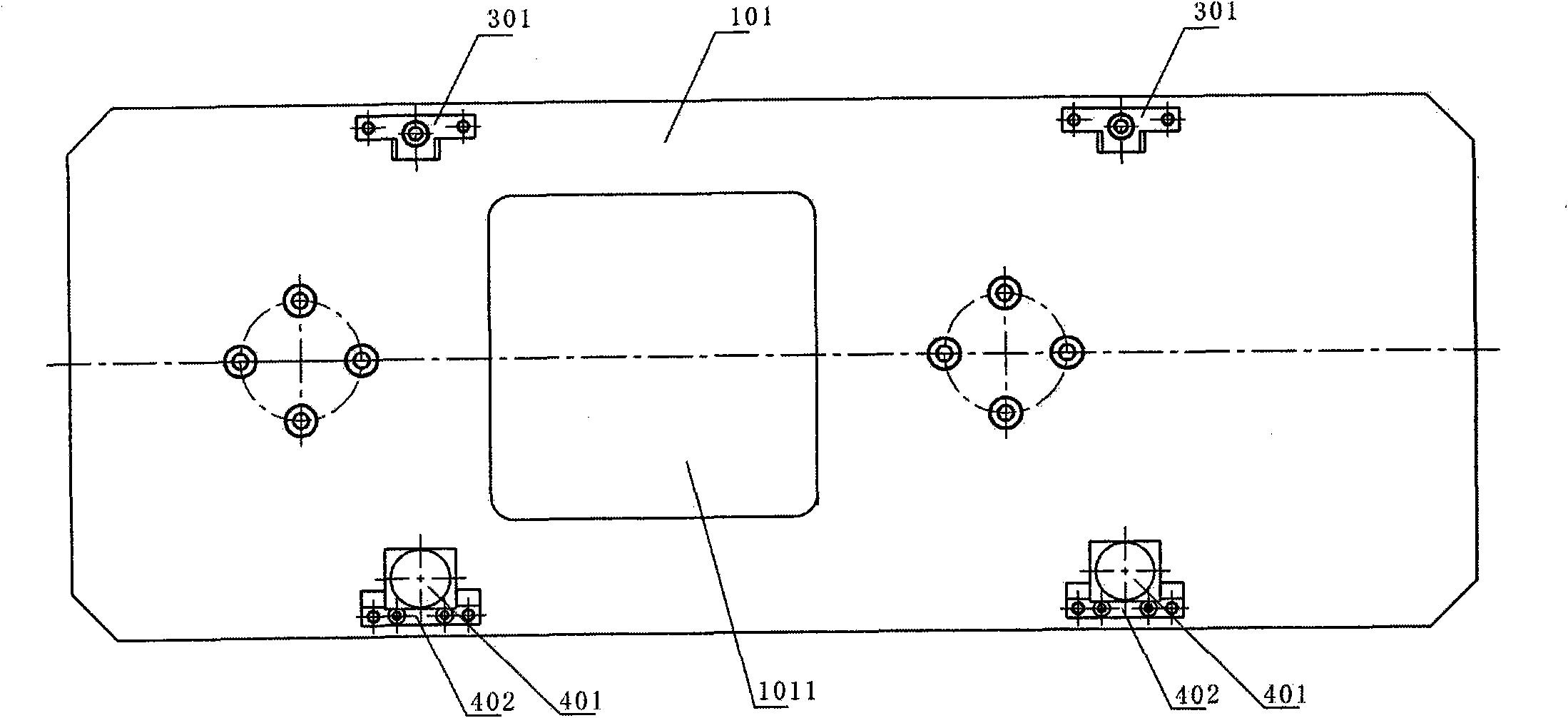
[0062] The present invention will be described in further detail below in conjunction with accompanying drawing:

[0063] The automobile shock absorber support projection welding floating tool provided by the invention is specially used for the projection welding of the automobile shock absorber support. It is composed of projection welding floating general base 1, replaceable automobile shock absorber bracket positioning frame 2, replaceable positioning frame positioning mechanism 3, wedge-shaped pressing mechanism 4, upper electrode seat 5 and lower electrode seat 6;

[0064] The replaceable car shock absorber bracket positioning frame 2 is installed on the projection welding floating universal base 1 through the replaceable positioning frame positioning mechanism 3 and the wedge-shaped pressing mechanism 4, and two symmetrically welded on the projection welding machine shell on both sides of the lower electrode plate 10. The supporting plate, the floating general base 1 for...


PUM


Abstract

The invention discloses an automobile shock absorber support frame projection welding floating tool, which relates to spot welding equipment and consists of a projection welding floating universal base, a replaceable automobile shock absorber support positioning frame, a replaceable positioning frame positioning mechanism, a wedge-shaped pressing mechanism, an upper electrode seat and a lower electrode seat, wherein the replaceable automobile shock absorber support positioning frame is arranged on the projection welding floating universal base through the replaceable positioning frame positioning mechanism and the wedge-shaped pressing mechanism, the projection welding floating universal base is arranged on a casing of a projection welder, the upper electrode seat is arranged under an upper electrode plate of the projection welder, and a lower electrode is arranged on a lower electrode plate of the projection welder. A spring is used for buffering in welding contact moment, thus the tool is stable and reliable, the salient point plastic deformation can not be caused, the salient point size is prevented from being changed by the upper electrode cylinder impact, and the welding strength stability is good.

Description

technical field [0001] The invention relates to spot welding equipment, in particular to equipment for projection welding of automobile shock absorber brackets, in particular to a floating tool for projection welding of automobile shock absorber brackets. Background technique [0002] Since the 1950s, the welding technology of China's automobile manufacturing industry has mainly been manual welding and resistance welding. The resistance welding process has the advantages of high production efficiency, uniform and reliable structure, etc., so it is widely used in the field of auto parts manufacturing. With the development of my country's automobile manufacturing industry, welding technology has made great progress, but there is still a huge gap compared with the automobile industry in developed countries. The automobile industry is a worldwide industry. In foreign countries, the French Renault Motor Company and the Japanese Nissan Motor Company have adopted a fully robotic c...

Claims


Application Information

Patent Timeline
IPC IPC(8): B23K11/14B23K11/36B23K11/30
Inventor 吴明伟翁金炉
Owner 浙江鼎信航天科技有限公司
Why Eureka
Try Eureka